That'll do it; where does it go?zulu said:http://parts.digikey.com/1/parts/761339-resistor-18k-ohm-5w-carb-comp-of183je.html
You are using an out of date browser. It may not display this or other websites correctly.
You should upgrade or use an alternative browser.
You should upgrade or use an alternative browser.
Well, what should I do with the T1RVT
- Thread starter zulu
- Start date
zulu
Senior Member
- Joined
- Dec 14, 2008
- Messages
- 2,181
- Reaction score
- 1,902
- Location
- NV west of Los Angeles
- Guild Total
- 4
; where does it go?
You'd think I would know the answer to that :lol:
I'm just working from my parts list, I can't remember exactly where that one goes, but I'll check this evening if you're curious.
Sorry ... it really wasn't a trick question ...zulu said:You'd think I would know the answer to that :lol:; where does it go?
 :lol: I tried looking around on that schematic but I'd like to put off another glasses prescription ... that schematic is a blur. :evil: Did you pick the value up off the schematic or by reading the color code?
zulu
Senior Member
- Joined
- Dec 14, 2008
- Messages
- 2,181
- Reaction score
- 1,902
- Location
- NV west of Los Angeles
- Guild Total
- 4
From the color code. I will find it in the amp and/or on the schematic, (which seems clear as a bell to me :wink: ) In case it's in a spot where I can sub a 15k or 20k.
I'm forgetting the amp doesn't match the schematic anyway ... :?zulu said:
there's no guarantee it's there in the first place!adorshki
Reverential Member
You Guys are STILL at it? What's it been like a week now without sleep? This is actually some kind of religious initiation like when the shamans make the poor wannabe eat something guaranteed to be really scary, right?!?! :lol: :lol:
Cap, you're a saint! :wink:
Cap, you're a saint! :wink:
- Joined
- Jul 30, 2007
- Messages
- 13,670
- Reaction score
- 3,101
- Location
- Philly, or thereabouts
- Guild Total
- 11
adorshki said:You Guys are STILL at it? What's it been like a week now without sleep? This is actually some kind of religious initiation like when the shamans make the poor wannabe eat something guaranteed to be really scary, right?!?! :lol: :lol:
Cap, you're a saint! :wink:
Next, cj teaches him the secret handshake. :wink:
Hi Zac ... didn't see these pics ... I guess I got distracted listening to the Stones ... We don't see that stuff because it isn't thereZac said:... the two brown wires ...I don't see anything like that, but I don't see like you see.juan said:should be a diode and then a small filter cap which I don't think I've seen so far
... Identification of the secondaries leaving the transformer: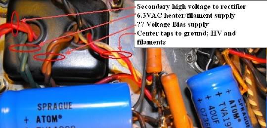
The two brown/bias wires; one should terminate on a diode, the other to ground; upper right is the schematic bias supply; you're ok for brown bias wires but no diode or bias supply filter cap which produce a negative voltage for the grid bias ... buttchoo don't have them. The two bias leads (neither grounded) terminate on those two resistors which, tied to the wiper of the hum balance pot, form a virtual center tap. There are two filament heater supplies in this amp. One source is the two green leads going to the rectifier then a dark brown and white to the ears of the hum balance pot, and then to the tube sockets. The other filament supply is taken from the junctions of the two brown bias leads and those resistors. This amp is strictly cathode-biased.
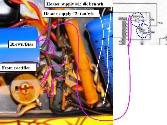
There are your two heater supplies running around the amp lighting up your tubes ... crossing each other in the green circle. Just going by the pics, it looks like the tan/white supply just runs along the back edge and feeds only the reverb preamp tube. I have no explanation what they're doing other than to say that the transformer, with its extra bias tap, was designed to support fixed bias but somebody decided it would be a cathode-biased amp and used that bias supply as an auxiliary filament supply ... take a little load of the primary filament supply. ??? That thing that looks like a piece of candy is a cap; don't know what it's doing and I don't think it's on the schematic ... which isn't especially reliable anyway.
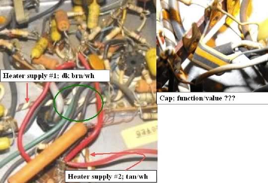
No big deal but supply #1 is made up of two wires that are twisted much more tightly than the other; they might be store-bought in that condition while the two wires that make up supply #2 ... well ... they look bench-made ... not following Default's Rule #56 for heater wiring; clamp two wires in a vice, chuck the two ends into an electric drill, and hit start button.
... and Gents .... about that secret handshake ........... :

zulu
Senior Member
- Joined
- Dec 14, 2008
- Messages
- 2,181
- Reaction score
- 1,902
- Location
- NV west of Los Angeles
- Guild Total
- 4
You'll tell me when I wear out my welcome, John?Is that the belt or the suspenders? I'll guess belt. no, suspenders.This amp is strictly cathode-biased.
That thing that looks like a piece of candy is a cap; don't know what it's doing and I don't think it's on the schematic
tastes like cherry, does that help?
kind of a crazy amp to be learning on, although next is an Ampeg B-25, it's so simple compared to this.There are your two heater supplies running around the amp lighting up your tubes --http://www.youtube.com/watch?v=PAbMazCRNso ... crossing each other in the green circle. Just going by the pics, it looks like the tan/white supply just runs along the back edge and feeds only the reverb preamp tube. I have no explanation what they're doing other than to say that the transformer, with its extra bias tap, was designed to support fixed bias but somebody decided it would be a cathode-biased amp and used that bias supply as an auxiliary filament supply ... take a little load of the primary filament supply. ???
Hi Zac: Compared to some post/reply exchanges with other T1 owners, this has been a pleasure and yes, I'll let you know when we're at the end of the T1 line. Cathode- v. fixed-bias ... it's mostly about people's preferences for one or the other and tied to their musical tastes and abilities; cathode bias is a tweedier, older, woodier, more easily distorted sound ... 'fart box' in the vernacular ... by contrast a fixed-bias amp stays cleaner longer distorting at higher volume better suited to lead play ... Swiss ... Gouda ... Camembert. Yes, belt no suspenders. Cherry cap you say? Those are good to eat ... avoid the ones that taste like lemon though :wink:
You can bring your B25 here too if you wish; yes - it's a clearer schematic (whew!) with a fixed-bias, sophisticated 'Baxendall'-type set of tone controls, and a pentode/triode 7199 (google it and read up) as the final gain stage/phase inverter ... my schematic says 7027 output tubes which have gone the way of the Snail Darter ... but 6L6s, except for possible bias considerations and whether the B25 uses pin 1 for a convenience tie point) will probably work (yes, that's the sound of Juan Juaffling ... :wink: ).
Learning curve; not completely certain but I think the T1s and T1 RVTs are the last point-to-point amps that Guild produced; later/more powerful models with split power and pre-amp chassis had p-t-p power supplies and circuit board preamps. The pcbs are a PITA to mess with ... :evil: J
You can bring your B25 here too if you wish; yes - it's a clearer schematic (whew!) with a fixed-bias, sophisticated 'Baxendall'-type set of tone controls, and a pentode/triode 7199 (google it and read up) as the final gain stage/phase inverter ... my schematic says 7027 output tubes which have gone the way of the Snail Darter ... but 6L6s, except for possible bias considerations and whether the B25 uses pin 1 for a convenience tie point) will probably work (yes, that's the sound of Juan Juaffling ...
:wink: ). Learning curve; not completely certain but I think the T1s and T1 RVTs are the last point-to-point amps that Guild produced; later/more powerful models with split power and pre-amp chassis had p-t-p power supplies and circuit board preamps. The pcbs are a PITA to mess with ... :evil: J
zulu
Senior Member
- Joined
- Dec 14, 2008
- Messages
- 2,181
- Reaction score
- 1,902
- Location
- NV west of Los Angeles
- Guild Total
- 4
Thanks capn, I'll tell you nobody has appreciated your help more than me. We're really close on the T1, tubes, caps and resistors on the way. Speakers are in good shape. One's a pyle (the 8"), the brand on the 12" slipped my mind . I'll record some soundbytes before and after the (cathode resistor bypass) cap change. With the trem caps I'm hoping to get a little more strength before thump. I've got some different preamp tubes to try out as well.
An interesting blog on the B25 if you're curious, according to this guy the circuit has a flaw of allowing frequencies as low as 9hz, easily 'rectified' with a cap swap.
http://stonemarmot.com/rants/?p=40
An interesting blog on the B25 if you're curious, according to this guy the circuit has a flaw of allowing frequencies as low as 9hz, easily 'rectified' with a cap swap.
http://stonemarmot.com/rants/?p=40
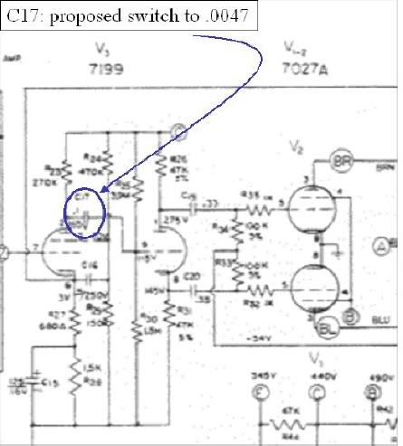
The Boyz at Stonemarmot say: "A better way is to change one of the caps inside the amp. I would recommend changing C17. This way you only need to change one cap to affect the response on both channels. If you change C17 from 0.1 microfarads to 0.0047 microfarads, you will limit the low frequency response of this stage to about 32 Hz and the whole amp to about 33 Hz. This will still comfortably pass the lowest note on a standard four string bass. This same change will also work on the Ampeg B-22-X and B-42-X." Hi Zac: well ... sure seems reasonable ... dat be de cap ... an interstage coupling cap that collects the signal from the first / pentode stage of the 7199 and connects it to the input of the second / triode stage while blocking the DC ... we don't want to listen to amplified DC. If you decide to make the switch, you want 600V rating on the replacement; if you don't find a .0047 in your favorite flavor, .005 will do:zulu said:An interesting blog on the B25 if you're curious, according to this guy the circuit has a flaw of allowing frequencies as low as 9hz, easily 'rectified' with a cap swap.
zulu
Senior Member
- Joined
- Dec 14, 2008
- Messages
- 2,181
- Reaction score
- 1,902
- Location
- NV west of Los Angeles
- Guild Total
- 4
Hey John, you mentioned it its common to see cathode bypass caps on the bias circuit with the positive connected to ground. Do you think The 220uf 100v electrolytic is installed backwards, and when I swap it, how should the polarity be oriented? Thanks Again, Zac
Thanks for looking into that ampeg article, I hope to start that one next month.
Thanks for looking into that ampeg article, I hope to start that one next month.
Hi Zac: you're mixing Guilds and Gibsons here ... in guitar amps, the only time an electrolytic cap is connected + to ground is in a bias supply circuit ... which you don't have. If you have an 130ohm resistor from one 6GW8 pin 7 to ground and your 220uf/100v electrolytic cap is connected + end towards the tube and - end to ground, you have a cathode resistor bypass cap and it's installed correctly. If you substitute, put the - end to ground and the + end on either pin 7; the two pin 7s must be jumpered ... wire running from one pin 7 to the other ... this is the case now, no?zulu said:Hey John, you mentioned it its common to see cathode bypass caps on the bias circuit with the positive connected to ground. Do you think The 220uf 100v electrolytic is installed backwards, and when I swap it, how should the polarity be oriented?
Bias filter cap; if your amp were set up like the schematic, of those two brown wires that are connected to those resistors ... one would be connected to ground and the other would be connected to a diode ...wichoo no got. Were this the case, there'd be a filter capacitor connected + to ground right after the diode filtering the negative DC voltage.
Hi Zac: just thinking out loud here but you've refreshed all the bypass cathode caps and I understand you have some new power tubes inbound. You might want to hold off on reducing that cathode bypass cap from 220uf/100v down to 25uf/25 or 50v. I can understand wanting to do as much maintenance as possible while the amp's on the bench but if you switch out the bypass cathode cap ... with your new tubes ... with your refreshed preamp cathode bypass caps, you're not going to get any sense of what any of these might have done individually to the amp's tone.
I mean, you can put the amp back together and see if you got any uptick from the cathode bypass caps you've already replaced. You can shut down and replace the power tubes without yanking the chassis, and fire back up and see what if any uptick you got from the tubes. I'm saying if you're ok with the amp's tone with that existing cap in it and since it's reasonably new and for the sake of appreciating what you've done so far, you might want to hold off ... you can still do it any time you want ... just a thought.
I mean, you can put the amp back together and see if you got any uptick from the cathode bypass caps you've already replaced. You can shut down and replace the power tubes without yanking the chassis, and fire back up and see what if any uptick you got from the tubes. I'm saying if you're ok with the amp's tone with that existing cap in it and since it's reasonably new and for the sake of appreciating what you've done so far, you might want to hold off ... you can still do it any time you want ... just a thought.
zulu
Senior Member
- Joined
- Dec 14, 2008
- Messages
- 2,181
- Reaction score
- 1,902
- Location
- NV west of Los Angeles
- Guild Total
- 4
Hi Zac: you're mixing Guilds and Gibsons here ... in guitar amps, the only time an electrolytic cap is connected + to ground is in a bias supply circuit ... which you don't have. If you have an 130ohm resistor from one 6GW8 pin 7 to ground and your 220uf/100v electrolytic cap is connected + end towards the tube and - end to ground, you have a cathode resistor bypass cap and it's installed correctly.
Doh! Just when I think I'm getting a handle on things.... BZZZZZZZZZT Wrong answer! Back to page 5 for a re-read.
capnjuan said:Hi Zac: just thinking out loud here but you've refreshed all the bypass cathode caps and I understand you have some new power tubes inbound. You might want to hold off on reducing that cathode bypass cap from 220uf/100v down to 25uf/25 or 50v. I can understand wanting to do as much maintenance as possible while the amp's on the bench but if you switch out the bypass cathode cap ... with your new tubes ... with your refreshed preamp cathode bypass caps, you're not going to get any sense of what any of these might have done individually to the amp's tone.
I mean, you can put the amp back together and see if you got any uptick from the cathode bypass caps you've already replaced. You can shut down and replace the power tubes without yanking the chassis, and fire back up and see what if any uptick you got from the tubes. I'm saying if you're ok with the amp's tone with that existing cap in it and since it's reasonably new and for the sake of appreciating what you've done so far, you might want to hold off ... you can still do it any time you want ... just a thought.
I see what you're saying. The amp is benched, but I made jumpers for the speakers so I have been running it with the chassis out. I actually planned on changing that cap before I change the power tubes, since I'm familiar with the tone using these tubes. I even thought it would be fun to (unscientifically) measure the amps frequency response before and after. Either way, I can swap the cap and play the amp and swap it back if I want, all without re-assembling the amp.
Can't say I notice any changes in tone so far. Maybe a bit more volume before break-up. The amps not real loud, though. I think my Epi valve junior might be louder.
Thanks J
zulu
Senior Member
- Joined
- Dec 14, 2008
- Messages
- 2,181
- Reaction score
- 1,902
- Location
- NV west of Los Angeles
- Guild Total
- 4
Also If I may ask about that cap in question. This cap is a bizarre value for it's location, is the 100v rating on the 220uF cap overkill, and that's why it's ok to go 50v there, or even 25v? What's going to affect the tone, changing the uF, right?
zulu
Senior Member
- Joined
- Dec 14, 2008
- Messages
- 2,181
- Reaction score
- 1,902
- Location
- NV west of Los Angeles
- Guild Total
- 4
Hi John, update. Last night I swapped out the off tolerance resistors and trem caps. I can't say for sure if I got more trem strength before "thump", but I think so.
I also switched out the cathode resistor bypass cap, from 220 uF 100v to 25uF/50v. I got a definite boost of volume which made it harder to evaluate the frequency response. A nice boost in volume, up to where I was hoping to get from the amp. Sounds good.
The amp is running very well. It has the least idle noise of any of my tube amps. I love the reverb.
Nice and clean, too. Almost no noticeable break up until 3/4 volume, and just crunchy when dimed.
I've got plans to play music a bunch this weekend, and will be putting the amp through it's paces, trying out different guitars, etc.
Maybe even record a bit.
Again, can't thank you enough.
I also switched out the cathode resistor bypass cap, from 220 uF 100v to 25uF/50v. I got a definite boost of volume which made it harder to evaluate the frequency response. A nice boost in volume, up to where I was hoping to get from the amp.
Sounds good.The amp is running very well. It has the least idle noise of any of my tube amps. I love the reverb.
Nice and clean, too. Almost no noticeable break up until 3/4 volume, and just crunchy when dimed.
I've got plans to play music a bunch this weekend, and will be putting the amp through it's paces, trying out different guitars, etc.
Maybe even record a bit.
Again, can't thank you enough.
Hi Zac; glad to hear it's running well. Can't guarantee results but if at some point in the future you want to take a shot at the trem strength, it's mostly a matter of replacing the caps in the trem circuit ... and making sure you have a fresh 12AX7 in there. Might not make an appreciable difference but you will have taken the most common cause of trem failure off the table. Do not know why last person put such a large value cathode cap in it; anybody who was strong enough technically to get your old can cap out without leaving any evidence would / should have been strong enough to understand the consequences of 220uf v. 25uf ... it's a puzzler ... good luck with your 'new' amp! John