Well, what should I do with the T1RVT

capnjuan

Gone But Not Forgotten
Joined
Nov 29, 2006
Messages
12,952
Reaction score
4
Location
FL
zulu said:
Okay there is a resistor that comes off pin 7 of the other power tube (this would be common with the + of that 22uF cap) ... but it doesn't go to ground, it goes to a terminal where it splits up about 4 different ways, none to ground ...
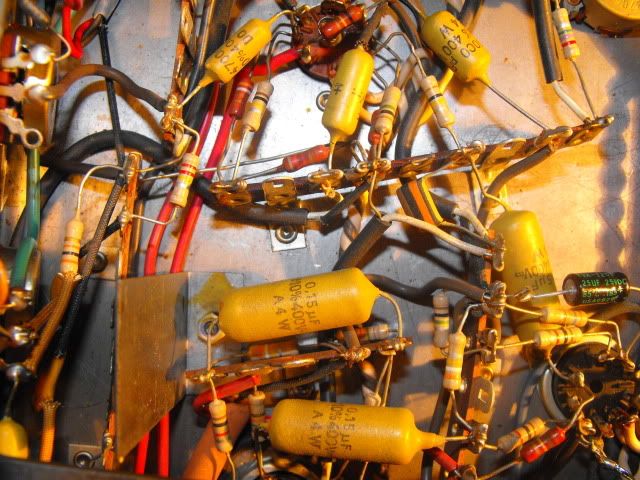
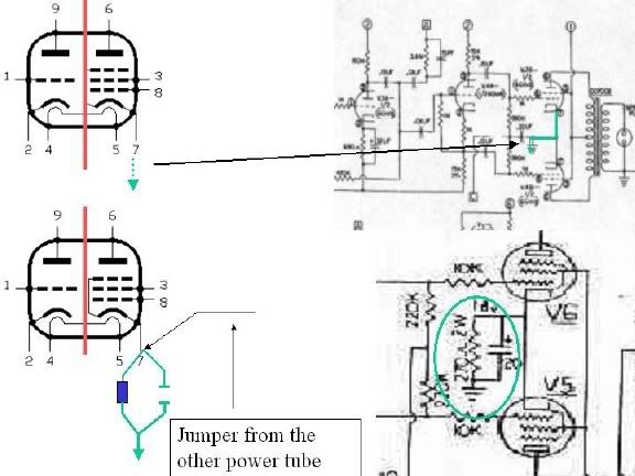
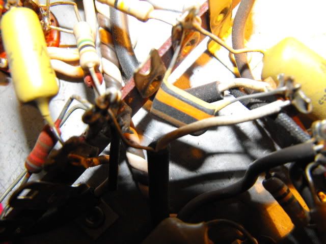
Hi Zac: "Never look a gift of a working amplifier in the chassis" St Leo of Fender ... Next time you tug the chassis out, take a couple of pics ... yes, I know that cross bar is in the way.

A few words about bias and why a resistor in parallel with that cap is of interest; when the amp is on but no signal present, there's current running from the plate (+) to the cathode (-) [and electrons flowing in the opposite direction ... more on them in a minute]. In a sense, it mimics a car at idle; set too low, the engine is sluggish responding to acceleration and if too high, not enough remaining rpm range to do much; in terms of tube bias these extremes are cold and hot respectively. For current to flow, the voltage on the cathode has to be higher than the voltage on the grid ... the pin where the musical signal goes in ... the amplified signal goes out via the plate.

There are two ways to ensure that the voltage on the cathode is higher than the voltage on the grid; 'force' a voltage to appear there by putting a resistor between the cathode and ground ... 'cathode bias' ... how it's done for most older and low-power student amps. For reasons of gain and frequency response, that resistor is commonly bypassed with a 25uf-50uf/25V electrolytic cap ... like the one showing in your amp that I asked you about. The other way to create a condition where the grid is more negative than the cathode / cathode more positive than the grid is by injecting a negative voltage on the grid and have no resistor between the cathode and ground ... schematically, this is how the T1 RVT is 'biased'.

Since there's no resistor on the cathode and it's connected directly to chassis ground, its voltage as a practical matter is 0 but the grid is negative with respect to the cathode because you and I just injected a negative voltage there .... 'fixed bias'. When the AC signal arrives at the grid, it 'irritates' the plate and the current flowing at idle increases proportional to the strength of the inbound signal but the voltage relationship between grid and cathode (grid lower than cathode) has to stay the same ... else the current won't flow at all. So; the term bias is a noun ... the voltage relationship or differential between the cathode and grid ... and a verb ... to measure/test/set that voltage relationship.

Belts and suspenders: occasionally you'll see amps that have both a negative voltage applied to the grid and a cathode resistor. Since there is an electrolytic capacitor of the type and rating commonly associated with cathode-bias schemes in your amp, weez looking to see if there's a resistor present too ... doesn't have to be but, despite the presence of a bias tap (two brown wires ... the source of a 'fixed bias' voltage) on the transformer, there could be one there nevertheless.

A word about our friends the electrons; the cathode is heated by the filaments; just like the heating elements on an electric stove top ... the filament sits behind the cathode and warms it so that it freely and happily gives up electrons that flow from chassis ground through the tube towards the plate in the opposite direction as the current; in the eight grade, we learned that DC current flows from postive / the anode / the + terminal to ground. While that current is flowing from the plate / anode to the cathode, there's a stream of electrons heading towards the plate ... the source of DC current and where the signal exits the tube.

Okay ... okay ... you're saying 'get to the damn point Juan willya' ... The musical signal is AC ... analog ... a sinusoidal waveform ... as the positive half of the waveform appears at the grid ... wait for it ... the electrons rushing from the cathode to the plate print an exact copy of the waveform on the plate/anode ... except that it's larger in amplitude. In a twin output tube design, the negative half of the waveform goes to the other output tube and it's copied by the stream of electrons onto the plate except larger in amplitude / volume whatever word you want to use. The current/electron flow principle applies to the preamp tubes as well.

I think your T1 is an earlier version; better grade 1w resistors in the preamp and the reverb section is hard-wired to the chassis and not sitting up on its own circuit board like most T1s and version 1 Thunderbirds and my interest in the presence/absence of a cathode resistor is about variations / evolution in the model's design. Occasionally, people have posted amps where the fixed bias scheme has been cowboyed into cathode bias ... rare but it happens.

J
 

zulu

Senior Member
Joined
Dec 14, 2008
Messages
2,170
Reaction score
1,870
Location
NV west of Los Angeles
Guild Total
4
Great post John, I'm doing cartwheels here as I put the pieces together in my head. I had a day's lesson on x-ray machines once, they work quite a bit like a vacuum tube.

my interest in the presence/absence of a cathode resistor is about variations / evolution in the model's design.

I'm benefiting hugely from your interest, and will photo the resistor and it's path this evening. the chassis is still out.

What do you think about replacing the bulgin connects with 1/4" mono phone plugs, that way I could try some different speaker cabs.
I assume the ground would have to be isolated from the chassis ground. Maybe some nylon washers.


I didn't want to come right out and ask you for a lesson on bias, but I was hoping! So, the adjustable bias on my evil twin must have something like a variable resistor between the cathode and ground? Or maybe it adjusts the voltage at the grid?

Thanks John!
 

capnjuan

Gone But Not Forgotten
Joined
Nov 29, 2006
Messages
12,952
Reaction score
4
Location
FL
zulu said:
... What do you think about replacing the bulgin connects with 1/4" mono phone plugs, that way I could try some different speaker cabs. I assume the ground would have to be isolated from the chassis ground. Maybe some nylon washers. Yes; 1/4" jacks w/ insulated throats ... not sure what the maximum AWG is for generic male phone plugs but I'd guess 18ga is about it; anyway get the best quality you can in that size ... OFHC ... sorry ... oxygen-free, high-conductivity stereo-style wire ... lots of strands. The speaker drops are one of the few opportunities to put good grade conductor in the signal path. Old (but not bold) amp techs will tell you it doesn't make much difference since you can't rewind the output transformer with better grade wire. And that's right but it's one of the few things/tweaks you can do to optimize performance. If you think this doesn't matter, then you can put any old stinky wire in there and when you go to show your amp off, you can say: "listen to my stinky old speaker wire ..." ... you get my point.

So, the adjustable bias on my evil twin must have something like a variable resistor between the cathode and ground? Or maybe it adjusts the voltage at the grid? The latter; in the bias supply circuit between the diode/filter cap and the grids.
8) J
 

zulu

Senior Member
Joined
Dec 14, 2008
Messages
2,170
Reaction score
1,870
Location
NV west of Los Angeles
Guild Total
4
Hi John. Okay, when I said:
zulu wrote ever so confidently:
Okay there is a resistor that comes off pin 7 of the other power tube (this would be common with the + of that 22uF cap) ... but it doesn't go to ground, it goes to a terminal where it splits up about 4 different ways, none to ground ...

I was wrong. It goes to ground, after tagging those .15 uF caps and resistors that end up at pins 8 and 9 on both power tubes.
here's overhead: the resistor (5w 130 ohm) in the lower left corner of the pic
DSCF2236.jpg


there.s shielding on it's lead. the other side of that terminal has the brown wire which makes a hard right turn under the yellow .15uF cap and connects to the terminal strip on the right. that terminal has a jumper that goes off the bottom of the pic and connects to, I'm sure you're way ahead of me... the - side of the 22uf cap ( which is 22uF in the schematic, but the actual cap is 220uF@100v.)

another view, peeking under the crossbar
DSCF2251.jpg

Occasionally, people have posted amps where the fixed bias scheme has been cowboyed into cathode bias ... rare


So, you say cowboys, eh? Converting fixed bias to cathode bias? We oughtta form a posse. Question, though, cathode bias is not adjustable bias, right? (except maybe changing the value of the resistor), and "matched" tubes are unneccesary for either scheme? edit - meant neccessary, matcheds tubes are neccessary
 

capnjuan

Gone But Not Forgotten
Joined
Nov 29, 2006
Messages
12,952
Reaction score
4
Location
FL
Hi Zac: well ... that 130 ohm / 5w resistor is original ... in the slide above, I mis-ID'd it as one of the power resistors ... this thing left the factory with Belts and Suspenders. Maybe it was such an early model that they were still working out some of the refinements.

Most cathode resistors on output tubes are between 250 and 500 ohms; the larger the value there, the higher the voltage on the cathode. This amp's cathode resistor is less than half of conventional value ... Guild solving the rest of the low grid / high cathode voltage relationship by adding negative voltage from the bias supply. There's a T1 RVT threaded here somewhere that somebody had cowboyed from fixed- to cathode-bias by disconnecting the bias supply and adding a cathode resistor and bypass cap.

The only comment I have is about that 220uf/100V cap ... tell me about the amp's tone; woody, bassy, dryish? The reason for asking is that that cap, besides influencing the tube's gain, effects frequency response too. Large value caps block high frequencies, small value caps block low frequency. I'm saying that I'd expect to see nothing larger there than 50uf so that cap value is exceptionally large; 10 times more than a conventional cathode resistor bypass cap. In the slide above on this page with the two tube drawings on the left; on the lower right is a 'cathode-biased' Gibson - note that its bypass cap is only 20uf ... one tenth of what your amp has. Further, it's also rated at 100V when 25V is the more commonly seen rating.

If you are up for a little Sherlock Fender, you might think about switching that cap out to something like 25uf/50v; it will probably bump the gain up/be a little louder and change the frequency response; be a little brighter, tinklier ... more treble. The 220uf/100v values aren't a safety issue but if that cap has been in the amp since you bought it; this is a matter of not knowing what you might be missing ... not saying that you'll like it any more or any less; but if you changed it, it would work safely but with a different tone signature. If you didn't like it, it wouldn't be any big deal to switch the 220uf/100v back in.
 

zulu

Senior Member
Joined
Dec 14, 2008
Messages
2,170
Reaction score
1,870
Location
NV west of Los Angeles
Guild Total
4
Hi John, thank you this is very interesting. I'm not good with descriptive tone terms, but while I haven't felt a lack of highs, the term woody seems to fit a bit. Either way, sounds like a fun way to tinker with the tone.

There's a T1 RVT threaded here somewhere that somebody had cowboyed from fixed- to cathode-bias by disconnecting the bias supply and adding a cathode resistor and bypass cap.
out of curiosity, would the reason be to add that bypass cap and experiment with the values?

In the slide above on this page with the two tube drawings on the left;
where's that slide again, please?
 

capnjuan

Gone But Not Forgotten
Joined
Nov 29, 2006
Messages
12,952
Reaction score
4
Location
FL
zulu said:
... out of curiosity, would the reason be to add that bypass cap and experiment with the values?
Sorry if I didn't make myself clear; I think your amp originally had that big brown resistor bypassed with an electrolytic that was replaced by that 220uf/100v and a negative voltage on the grid. Before going any further, you need to trace the two brown wires coming from the transformer and confirm that they are actually connected; should be a diode and then a small filter cap which I don't think I've seen so far. It's common practice when recapping to replace the bypass caps too but other than the tech might not have had a closer value, I can't think of why anyone would want such a large value cap there ... where 20 to 25 (occasionally 50) uf/25v is the norm.

In general terms; cathode bypass caps - on either/both the preamp or power tubes - filter out high frequencies it being that such frequencies don't pass through large value caps. The result is a bassier, more mid-rangey, woody, boomier tone ... like rolling off the treble on the guitar's tone pot. I guess I'm saying that it isn't clear why you have the value cap you do; I was only suggesting that without too much trouble, you could match its cathode bypass cap to what is more commonly seen ... without operational risk but with an expectation of getting a different baseline tone from your amp.

This one: the Guild output section above right, Gibson GA19 lower right:

T1ZG.jpg
 

zulu

Senior Member
Joined
Dec 14, 2008
Messages
2,170
Reaction score
1,870
Location
NV west of Los Angeles
Guild Total
4
Before going any further, you need to trace the two brown wires coming from the transformer and confirm that they are actually connected; should be a diode and then a small filter cap which I don't think I've seen so far.


the two brown wires from the input transformer are connected, seems to me as per the schematic or close. The brown wires emerge from under the Blue Sprague and attach to the terimal strip (lower center of pic). Through resistors they split to the hum balance pot. from either the terminal strip, or the hum balance pot, they are connected to every valve in the amp via the twitsy brown and white wires.

DSCF2253.jpg


should be a diode and then a small filter cap which I don't think I've seen so far
I don't see anything like that, but I don't see like you see.


I don't think this is in the bias circuit, but what is the multi colored component in the center if this pic?
DSCF2255.jpg

Thanks J
 

coastie99

Enlightened Member
Joined
Jan 1, 2006
Messages
8,662
Reaction score
27
Location
Greymouth, West Coast, Newsyland
capnjuan said:

:D :D :D B-side of one of the early Stone's singles, can't remember which. A tune I've always liked.

I particularly like their take on "That's How Strong My Love Is" from OOOH's.

"Superficial(ly ?) thinkin' " Hope not !

Ya know what I'm thinking ? One of the great pleasures of Geezerhood is the vast storeroom of music that I have in my head.
 

zulu

Senior Member
Joined
Dec 14, 2008
Messages
2,170
Reaction score
1,870
Location
NV west of Los Angeles
Guild Total
4
Nice little Stones interlude. I have an old bootleg, a blues number that is extremely profane.

Hey capn, I'm ordereing replacements for those caps in the trem circuit. Seems the Orange Drops have the closest values. Okay to use those, and is it okay to use 400v in place of 200v if the picofarads are the same?

http://www.tubesandmore.com/scripts/fox ... EE04=0400V

What do you think of these for speaker jacks
http://www.tubesandmore.com/scripts/fox ... tem=S-H551

I'm going to try a 25 uF 50v cathode resistor bypass cap as suggested.

I've got some very nice power tubes coming that will be fun to try out. :D

Thanks Guys!!
 

zulu

Senior Member
Joined
Dec 14, 2008
Messages
2,170
Reaction score
1,870
Location
NV west of Los Angeles
Guild Total
4
Found everything at AES except for an 18k ohm 1/2 watt resistor. Have to order one from somewhere else, but AES has had everything else.
 

capnjuan

Gone But Not Forgotten
Joined
Nov 29, 2006
Messages
12,952
Reaction score
4
Location
FL
zulu said:
Nice little Stones interlude. I have an old bootleg, a blues number that is extremely profane.
Always good to have a little music in any thread. 8)

Seems the Orange Drops have the closest values. Okay to use those, and is it okay to use 400v in place of 200v if the picofarads are the same? Yes; although 600V at the same uf will give you a little more margin for saftey. The trem circuit doesn't carry the audio signal ... no need to worry about tone quality ... trem caps are worker bees.


What do you think of these for speaker jacks
http://www.tubesandmore.com/scripts/fox ... tem=S-H551 I like 1/4" phone jacks better although I guess I can't really think of a good reason ... but they look like they'll work; not sure how big a chassis hole is under those Bulgin jacks ... might be looking at some washers although washers might be necessary whichever jack you used. If you use washers in either case, the length of threading starts to matter; washers top and bottom might prevent the nut from starting on the threads. This one has a longer bushing: http://www.tubesandmore.com/scripts/fox ... m=W-SC-L11

I'm going to try a 25 uF 50v cathode resistor bypass cap as suggested. Have fun; will be surprised if it doesn't make a noticeable difference. Not saying you'll like it any more or less ... if you get a change it voice ... it will be a Gouda v. Swiss thing ...

I've got some very nice power tubes coming that will be fun to try out. So I heard; other than having to watch your wimmins, you're are dealing with the most reputable source south of the equator ... maybe north of it too ... Your source recently laid two EL84s on me; a Mullard and a Telefunken ... nothing finer in all of Tubedom. He's the Man :wink:
 

zulu

Senior Member
Joined
Dec 14, 2008
Messages
2,170
Reaction score
1,870
Location
NV west of Los Angeles
Guild Total
4
Thanks capn
other than having to watch your wimmins
Thanks for the warning!

He's the Man

+1

not sure how big a chassis hole is under those Bulgin jacks

washers will be required. I'm also considering re-locating the main speaker output next to the reverb speaker out.

Am I correct in my understanding that having a tube rectifier negates the need for a standby? For extended use,is it better to turn the amp off during breaks?
 

capnjuan

Gone But Not Forgotten
Joined
Nov 29, 2006
Messages
12,952
Reaction score
4
Location
FL
zulu said:
Found everything at AES except for an 18k ohm 1/2 watt resistor. Have to order one from somewhere else, but AES has had everything else.
It's just my opinion but I think the T1 RVT and Thunderbird were designed from scratch by/for Guild; and not really borrowing much from other designs of the day. If so, it would explain how come there are so many oddball R values not seen elsewhere: 14K, 18K, 92K ... and others. Where are you picking up that 18K?
 

capnjuan

Gone But Not Forgotten
Joined
Nov 29, 2006
Messages
12,952
Reaction score
4
Location
FL
zulu said:
.... that having a tube rectifier negates the need for a standby? For extended use,is it better to turn the amp off during breaks?
Yes and yes; until the filament in the rectifier gets hot, it won't produce DC ... unlike an amp with ss diode rectifier which produces DC the moment it's turned on. The slow warm-up prevents our friends the electrons from being stripped off the cathodes of the preamp and power tubes as they are when a ss rectifier/tube amp is switched directly on bypassing standby.
 
Top