You are using an out of date browser. It may not display this or other websites correctly.
You should upgrade or use an alternative browser.
You should upgrade or use an alternative browser.
Well, what should I do with the T1RVT
- Thread starter zulu
- Start date
zulu
Senior Member
- Joined
- Dec 14, 2008
- Messages
- 2,170
- Reaction score
- 1,870
- Location
- NV west of Los Angeles
- Guild Total
- 4
you should see the poor chicken!!
zulu
Senior Member
- Joined
- Dec 14, 2008
- Messages
- 2,170
- Reaction score
- 1,870
- Location
- NV west of Los Angeles
- Guild Total
- 4
my continuity tester kept beeping this pattern at me.
.-.. --- --- ... . / ..-. ..- ... .
.-.. --- --- ... . / ..-. ..- ... .
zulu
Senior Member
- Joined
- Dec 14, 2008
- Messages
- 2,170
- Reaction score
- 1,870
- Location
- NV west of Los Angeles
- Guild Total
- 4
After a few days away, I wanted to try again, so I removed the death cap. Amp still wouldn't power up. I wanted to test something so I got through testing almost all the resistors when I thought of testing the continuity of the fuse. Fuse was fine, but had the slightest wiggle at one end. testing between the fuse brackets produced the bb--bb--bbe-bbeeeeep.
 .... :roll: , but
I'm pretty sure that took care of the intermittent problem.
Yay! Muchos Gracias Juan mi e-amigo!
I'm going to change that one other cap on the speaker. There are a number of resistors out of tolerance (Rad Shaq okay for those?), and I need to search up thread on "trem thump" that I found a while back. But basically, it's Tone Time.
Hola Z; nothing wrong w/ RadShaq but you may have some trouble with odd values and higher wattage ratings. If they no have, Antique Electronics Supply will; nothing less than .5 watt; greater if original has higher rating. It's possible that the unidentified pot is either a master volume for the trem or, considering that yours is an early model and the fact that the bias voltage runs through the trem 'strength' control, that it could be a bias control. If for volume, it would have been intended as a set-it-and-forget-it never-higher-than control; if for bias, we'd want to leave it alone for now leaving it as something to mess with if you can't get the trem de-thumped.zulu said:... Fuse was fine, but had the slightest wiggle at one end. testing between the fuse brackets produced the bb--bb--bbe-bbeeeeep. I'm pretty sure that took care of the intermittent problem. To quote a famous amp tech: "It's always something" L. Fender I'm going to change that one other cap on the speaker. Si; bueno. There are a number of resistors out of tolerance (Rad Shaq okay for those?), and I need to search up thread on "trem thump" that I found a while back.
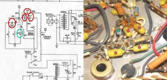
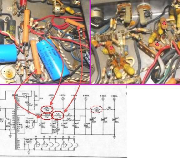
Because the electronics that generate the trem's owaowaowa are always on whether the function is engaged or not, its bits and pieces are subject to a lot of wear and tear and the most common cause of trem malfunction is one or more of the trem caps giving it up. You have two choices; find the bad one by Testing Them or replacing all of them; the later, while a little less 'green', will keep you from having to go through the same exercise when another fails. Your choice ... The four caps in red circles on the left are the four caps ID'd on the right; can't tell which is which but all four have to be functional. The green circle cap is a cathode resistor bypass cap; don't know if you changed this one or not; if not ... observing polarity; - to ground.
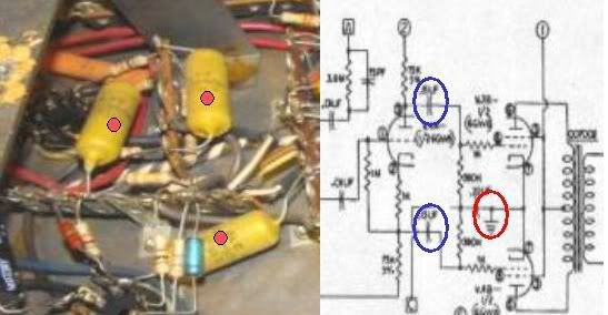
The trem works by messing with the bias ... roughly the relative voltage differential between the voltage on the power tube's grid where the musical signal appears and the cathode; the tube's connection to ground. The trem in this amp makes the voltage on the grids go up and down; in your amp, there are two coupling caps and one bias/trem cap near the output tubes. From the pic, I can't tell which are which but only one of the three that are marked has one end connected to ground. If fiddling with the four trem caps ID'd above doesn't fix the problem, then find which of the three caps below is the bias-related cap and replace it:
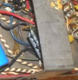
I think this is the bias supply filter cap that has been refreshed; can you confirm? + lead should be connected to ground ... as a general rule, bias circuits are the only place you find electrolytics with the + lead to ground:
As ever, there are bold amp techs and there are .... :wink: J
zulu
Senior Member
- Joined
- Dec 14, 2008
- Messages
- 2,170
- Reaction score
- 1,870
- Location
- NV west of Los Angeles
- Guild Total
- 4
Again, the thoroughness of your replies is educating me while helping with my amp, thank you.
1. how can I tell the wattage rating of a resistor.
2. has that capacitor test worked well for you? OK to leave cap connected for ohm test I suppose?
I played with it a little, couldn't get it to affect the sound. The two resistors connected to it are off tolerance (down 50%)
I'll check that this evening. Interesting.
.. guys like Coastie??

thanks John.
1. how can I tell the wattage rating of a resistor.
2. has that capacitor test worked well for you? OK to leave cap connected for ohm test I suppose?
It's possible that the unidentified pot is either a master volume for the trem or, considering that yours is an early model and the fact that the bias voltage runs through the trem 'strength' control, that it could be a bias control.
I played with it a little, couldn't get it to affect the sound. The two resistors connected to it are off tolerance (down 50%)
I think this is the bias supply filter cap that has been refreshed; can you confirm? + lead should be connected to ground ... as a general rule, bias circuits are the only place you find electrolytics with the + lead to ground:
I'll check that this evening. Interesting.
As ever, there are bold amp techs and there are .... :wink: J
.. guys like Coastie??
thanks John.
I'll check that this evening. Interesting. Ok.zulu said:1. how can I tell the wattage rating of a resistor.
In these old amps, everything 1 watt or greater is marked with its rating; everything else is .5 watt.
2. has that capacitor test worked well for you? OK to leave cap connected for ohm test I suppose?
If the meter has the setting, it's how they are tested; must disconnect one end ... in part why sometimes I lose patience and clear-cut ... in trem circuits I replace them all because the idea of my going in there again to replace another ... or making somebody else replace another when I could have done 2/3/4 just as easily ... everybody feels differently though ... some feel it's better to leave as much original as possible ... some say the world will end in fire ...
I played with it a little, couldn't get it to affect the sound. The two resistors connected to it are off tolerance (down 50%)It's possible that the unidentified pot is either a master volume for the trem or, considering that yours is an early model and the fact that the bias voltage runs through the trem 'strength' control, that it could be a bias control.
Well ... you know what to do with out-of-tolerance resistors...
[quote:3lys88le]I think this is the bias supply filter cap that has been refreshed; can you confirm? + lead should be connected to ground ... as a general rule, bias circuits are the only place you find electrolytics with the + lead to ground:
.. guys like Coastie?? [/quote:3lys88le]As ever, there are bold amp techs and there are .... :wink: J
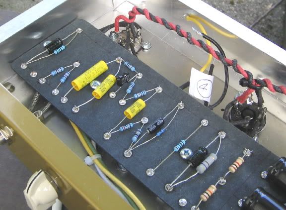
When you and I grow up, we should both hope to be like Coastie; a view of a work-in-progress at Wuzzatronics Labs, the best ampworks on the south island;
zulu
Senior Member
- Joined
- Dec 14, 2008
- Messages
- 2,170
- Reaction score
- 1,870
- Location
- NV west of Los Angeles
- Guild Total
- 4
When you and I grow up, we should both hope to be like Coastie; a view of a work-in-progress at Wuzzatronics Labs, the best ampworks on the south island;
Agreed. that is some beautiful work. Coastie is also a joy to correspond with. Much respect.
In these old amps, everything 1 watt or greater is marked with its rating; everything else is .5 watt.
didn't see any markings that I recognised. There are a few resistors that are dark red, with standard color bands, and a few that are larger than others.
Hi Z; the higher rated resistors commonly found in the power supply; 7w, 10w, and 1w on the left (the 7w and 10w might be mis-ID'd vice and versa) ... you might have to bend/roll the resistor to see the markings. The 4th resistor ID'd at the bottom in dotted circle is at the reverb amp can capacitor ... not in either pic. On the right are several resistors that are probably 1w ... larger contrasted with all the carbon composition red and tan smaller ones. Not uncommon for amp and schematic not to match 100%. The ones one the right are probably plate resistors; used to drop the raw dc voltage to 125-175 volts for the tubes ... they are not directly in the signal path.zulu said:... didn't see any markings that I recognised. There are a few resistors that are dark red, with standard color bands, and a few that are larger than others.
zulu
Senior Member
- Joined
- Dec 14, 2008
- Messages
- 2,170
- Reaction score
- 1,870
- Location
- NV west of Los Angeles
- Guild Total
- 4
I think this is the bias supply filter cap that has been refreshed; can you confirm? + lead should be connected to ground ... as a general rule, bias circuits are the only place you find electrolytics with the + lead to ground:
Zac's version of what Zac perceives:
the power tubes are wired together at each one's pin 7 (V3 and V4, I think)
pin 7_____________________pin 7
|
|
|
+
Cap 220 uF 100v
- to ground
The cap is connected positive to pin 7 of V3 or V4 (whichever one is at the back of the amp, I haven't figured that out)
negative to a shared terminal, then to chassis ground.
zulu
Senior Member
- Joined
- Dec 14, 2008
- Messages
- 2,170
- Reaction score
- 1,870
- Location
- NV west of Los Angeles
- Guild Total
- 4
also, is that a non polarized cap in the schematic? Thanks John.
Hi Zac: that cap is typically used in conjunction with a resistor in parallel; is there a resistor there? That's the pinouts of a 6GW8 up top (ignore triode section to left) v. the schematic ... below; your cathode cap and a yet-to-be-confirmed / identified cathode resistor (in blue) v. a schematic for a Gibson GA19; a cathode-biased, Class B amp ... You also have a bias tap in the power supply - the brown twisted pair and somewhere a bias diode and filter cap ... if you have a resistor in parallel with that electrolytic cap, you have a belts-and-suspenders bias scheme :shock: <sigh>zulu said:... the power tubes are wired together at each one's pin 7 negative to a shared terminal, then to chassis ground.
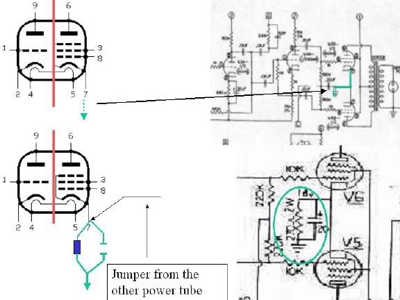
Yes; it's a non-polarized cap in the schematic; the one you have in there I don't think was intended as a replacement; it would be in addition to the non-polarized cap. Your amp has lots of things that don't match the schematic; 1w resistors in preamp, chassis-mounted unidentified pot, reverb amp hardwired to chassis and not on its own circuit board. It would be helpful to know whether you have a resistor in parallel with that 22uf cap. That cap looks new but it could still be shot/defective and, if so, could be a cause of your intermittent ... wtf ... many things could be but if you change it out and I suggest you do so, you will either fix the problem or rule something out while knowing that you have a new part that shouldn't be a source of concern down the road.
Finishing the voltage checks - where we were when the lights went out - would rule out the power supply and distribution ... that would be a good thing to do leaving the signal chain as the source of the problem. J
zulu
Senior Member
- Joined
- Dec 14, 2008
- Messages
- 2,170
- Reaction score
- 1,870
- Location
- NV west of Los Angeles
- Guild Total
- 4
Hi John. I don't think there is a resistor in parallel with that cap. There certainly is not one connected at the same pin with the resistor, only the jumper to the other pin 7. To be sure I think I need to trace whatever comes off the other tube at pin 7, maybe there is a resistor that terminates at the ground with that 22 uF cap. Does that make sense?
The amp ran over two hours last night. I'm quite sure that loose fuse was causing the intermittent problem.
(not sure if the image copied, bit of a BBS noob too)
green circle cathode resistor bypass cap is one that I changed. That trim pot there is the trem strength, or the way I see it, sets the 'range' of the trem strength on the front panel. Manipulating that pot I was able to eliminate the "trem thump" while maintaining a decent range of strength adjustment up front (IOW front strength knob full up, turn trim pot up until thump occurs, then back off a little). I'm debating on changing these (4 caps) now with the trem working good, although it would be interesting to see if new caps would provide increased trem 'strength before thump'
more in a moment
thanks J
The amp ran over two hours last night.
. The four caps in red circles on the left are the four caps ID'd on the right; can't tell which is which but all four have to be functional. The green circle cap is a cathode resistor bypass cap; don't know if you changed this one or not; if not ... observing polarity; - to ground.
Image
(not sure if the image copied, bit of a BBS noob too)
green circle cathode resistor bypass cap is one that I changed. That trim pot there is the trem strength, or the way I see it, sets the 'range' of the trem strength on the front panel. Manipulating that pot I was able to eliminate the "trem thump" while maintaining a decent range of strength adjustment up front (IOW front strength knob full up, turn trim pot up until thump occurs, then back off a little). I'm debating on changing these (4 caps) now with the trem working good, although it would be interesting to see if new caps would provide increased trem 'strength before thump'
more in a moment
thanks J
Or ... if you wanted to sell it, you could say that yours is factory-equipped with Thumper ... formerly the hottest thing in built-in amp effects ..... maybe not :wink: My pleasure Zac.zulu said:Hi John. .... I think I need to trace whatever comes off the other tube at pin 7, maybe there is a resistor that terminates at the ground with that 22 uF cap. Does that make sense? Yes; makes sense - could go from 'other' pin 7 to ground. Might not be there but need to know. The amp ran over two hours last night.I'm quite sure that loose fuse was causing the intermittent problem. Yippie! Green circle cathode resistor bypass cap is one that I changed. OK. That trim pot there is the trem strength, or the way I see it, sets the 'range' of the trem strength on the front panel. Manipulating that pot I was able to eliminate the "trem thump" while maintaining a decent range of strength adjustment up front (IOW front strength knob full up, turn trim pot up until thump occurs, then back off a little). I'm debating on changing these now with the trem working good, although it would be interesting to see if new caps would provide increased trem 'strength before thump'; Ok; acts a little like a master volume ... a volume control in series setting the upper bound of the effect.
zulu
Senior Member
- Joined
- Dec 14, 2008
- Messages
- 2,170
- Reaction score
- 1,870
- Location
- NV west of Los Angeles
- Guild Total
- 4
will report back.Yes; makes sense - could go from 'other' pin 7 to ground. Might not be there but need to know
you can say that again!Yippie!
:lol:factory-equipped with Thumper ... formerly the hottest thing in built-in amp effects
FWIW
The other trim pot ( hum balance? ) will induce a small amount of hum, at both extremes of trim, with the amp at high volume. just a small amount.
of all the resistors, I found five (little guys) out of tolerance, none of the higher watt ones were out.
the speaker connection plugs ( I can't recall the name of those) aren't tight enough, a stiff breeze could blow the speaker plugs out of the chassis plugs. can they be pinched tighter, or should be replaced?
Thank you
They are known as Bulgin connectors and again at Allied ... URL long form; http://www.newark.com/jsp/brand/brands. ... =TC|14596|{keyword}|{placement}|{ifcontent:C}{ifsearch:S}|b|{creative}&s_kwcid=TC|14596|bulgin||S|b|4482593236zulu said:... the speaker connection plugs ( I can't recall the name of those) aren't tight enough, a stiff breeze could blow the speaker plugs out of the chassis plugs. can they be pinched tighter, or should be replaced?
I considered these previously and dismissed them because of the wire size limit; used mostly in industrial and marine applications. They still make 2 pins plus ground male and female hardware. You can try pinching (or spreading) the male pins to re-tension them. If that doesn't work, next time Gary has his T1 RVT chassis out, he can take a couple of pics of the work-around in his amp which is taking wiring strips, bolting/screwing them to the chassis, terminating the + and - output transformer leads to the wiring strip, and adding speaker drops to the speakers. That way, you can increase the length of the speaker feed wiring without stressing the Bulgin connectors at every chassis out/in event. You can also use audio-quality speaker wire instead of those cheesey little #20s or whatever they are.
adorshki
Reverential Member
MAN are you guys still up? You've been at this all night! WH-O-O-O-AH... make that several nights! :lol:
zulu
Senior Member
- Joined
- Dec 14, 2008
- Messages
- 2,170
- Reaction score
- 1,870
- Location
- NV west of Los Angeles
- Guild Total
- 4
lol I keep waiting for capnjuan to say "phooey, you're on your own!" but until then....MAN are you guys still up? You've been at this all night! WH-O-O-O-AH... make that several nights!
she's sounding great John, I appreciate it so much.Hi Al; jes' trying to make sure Zac's Thunder thunders ...
Hi John. .... I think I need to trace whatever comes off the other tube at pin 7, maybe there is a resistor that terminates at the ground with that 22 uF cap. Does that make sense? Yes; makes sense - could go from 'other' pin 7 to ground. Might not be there but need to know.
Okay there is a resistor that comes off pin 7 of the other power tube (this would be common with the + of that 22uF cap)
but it doesn't go to ground, it goes to a terminal where it splits up about 4 different ways, none to ground. As hard as I stare at the schematic, I can't place it.
zulu
Senior Member
- Joined
- Dec 14, 2008
- Messages
- 2,170
- Reaction score
- 1,870
- Location
- NV west of Los Angeles
- Guild Total
- 4
if you have a resistor in parallel with that electrolytic cap, you have a belts-and-suspenders bias scheme <sigh>

Now, see, whatcha got here, see, is a whatcha call a belts and suspenders bias scheme see, It's a con, see, and I'm gonna cap 'em all, see.
Like that?