New member with new toy ( Thunder 1)

Joined
Feb 17, 2009
Messages
9
Reaction score
0
Location
Erie, PA
Some additional comments on the amp I have.

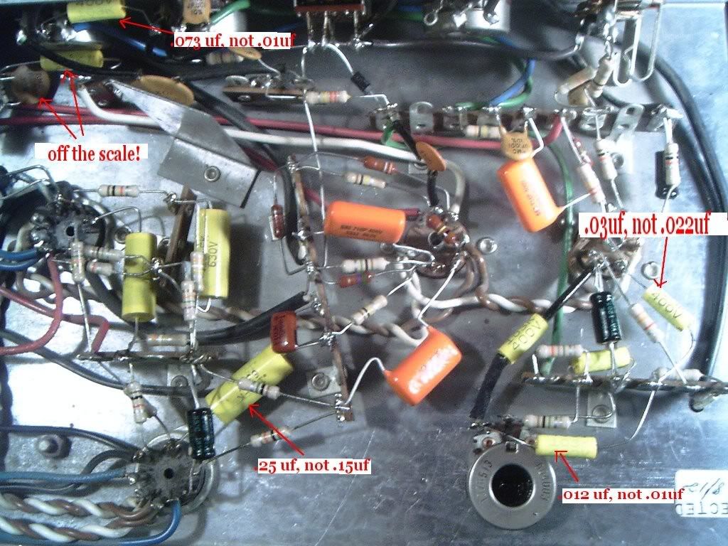
Modifications that I found were the input jack circuit rearrangement, the addition of the cathode bias scheme on the power tubes, the addition of two parallel jacks in the rear, the tremolo circuit affecting the signal between the tone stack and V2 (as opposed to adjusting the bias). Several of the component values were also different.

One original pot on the bottom of the chassis is for the trem circuit, but I didn't know what to label it, so my schematic just shows it as ??? Trem for now. I'll update that once I learn what it does.

Also, on the power on light, my schematic shows an LED, but it's just a regular bulb. I didn't have a symbol for it, so just substituted in this case.
 

capnjuan

Gone But Not Forgotten
Joined
Nov 29, 2006
Messages
12,952
Reaction score
4
Location
FL
Delta362 said:
... an older Guild Thunder 1 that he wants me to get working again ... perhaps do a few mods to it ... was clearly modified ... ExpressSCH ... was loud hum and buzz. I'll be redoing the power section caps, as well as most of the other caps in the amp, due to the age. The owner wants a little less brightness as well as add some more gain to it. Any suggestions on that would be welcome.
Hi Mike and welcome to LTG! Congratulations on your clear schematic; I gotta get better with ExpressSCH ... I guess it shows :oops: . If I may and knowing how much older amps bounce back with fresh power, I might suggest that you consider holding off any gain or brightness mods until you and friend have a better idea of what the amp can do when it's closer to baseline. As you know, bass pulls heavily on the power supply caps and if they are old and weak, you'll just get an amp that handles highs / brights reasonably well (that's all you hear) because they are less dependent on reserves of juice. Anyway, just a thought.

Can't tell for sure by looking but maybe the preamp out wiring is all that's new? Maybe the rectifier socket? The biggest difference between your amp and Brendan's is the trem circuit's tie-in with the line. Yours looks stock but so does his and neither matches the Guild schematic. :evil: Anyway, you are welcome to pitch in on getting Brendan's running; very soon he'll have all new trem components ... but no trem. If / when you get actual plate voltages ... well .. that'd be a nice add to your schemo and a boost to Brendan who is going to start all his hot-checking.

Finally, not sure what your man means by 'gain'. There are gainy amps that sound like the speaker is ready to jump through the grillcloth ... edgy, swirly ... and there's gain in the volume / loudness sense. If he wants the latter, you might look into a fresher, more efficient Emi or Weber ceramic speaker; might as well hear all of what the circuit has before tinkering with it electronically; might be that after the caps and a fresh speaker - which is a good idea anyway - he might be completely happy with it. Good luck and again, welcome! CJ
 
Joined
Feb 17, 2009
Messages
9
Reaction score
0
Location
Erie, PA
Thanks for the welcome, CJ!

I was re-reading the thread and have checked my amp's trem circuit again and compared it with Brendan's. The diode that is attached to the trem switch is connected to ground on the anode side. The cathode of the diode (side with the line) is attached to the NO (normally open) contact (top) of the middle column on the switch. The common is connected to the bass pot wiper via a 22k in series with a .005 cap.

I see my schematic has a few errors in that section as well so I'll trace that out this morning and see if I can fix it.

As for the trem circuit not working properly, I'll give it some more thought and see if I can offer any suggestions.

CJ, I agree with the assessment on getting a baseline before taking treble off. The power supply will need a complete overhaul before changing the tonal characteristics of the other circuits. As for the gain, he was wanting a little more grit to it. Stated that it's a clean amp that gets just a little bit of breakup, but not until the amp is way up. He is hoping to have just a bit more overdrive to it at a lower volume, but still maintain the ability to clean up (I'd roll back the guitar volume knob slightly for that).
 
Joined
Feb 17, 2009
Messages
9
Reaction score
0
Location
Erie, PA
I thought I had some mistakes on the trem circuit, but I've traced it out several times and I keep coming up with the same thing. I'm not quite following how the circuit is working as it is connected.

Brendan, do you have a parts list of the caps you purchased? I found the cap can and the other axial cap on the power supply at AES. It's the other caps that I'm slowly questioning their values. Typically I go to Mouser to get things like that, but I may just get all the caps, not just the cans, at AES. I saw the 3PDT switches you ordered and picked myself up a set of those. Thanks for posting that!

Thanks,
Mike
 

Brendan

Junior Member
Joined
Nov 29, 2008
Messages
63
Reaction score
0
Hi Mike,

Thanks for posting pics of the innards. I was kind of surprised at how different the tremolo circuit is as well as a few other small details. I think that's 3 different tremolo designs we've seen for this model. After you have that freshened up with new caps, I would love to hear how deep that tremolo can get. I played my amp for an hour last night and it sounded great - even the tremolo. I just wish I could adjust it a hair deeper without getting the dreaded thump. I can only open up that rear pot half-way at this point. This was my first time inside an amp and I've really enjoyed the project. I know the trem will get sorted eventually. Here's a listing of the caps I ordered:
C-EC40X4-350 CAPACITOR, ELECTROLYTIC, 40/40/40/40 UF @350 VDC (1)
C-ET47-500-IL CAPACITOR, AXIAL LEAD ELECTROLYTIC, 47µF @ 500VDC,ILLINOIS(1)
C-PD033-400CAPACITOR, POLYPROPYLENE FILM, .033 µF @ 400 V (716P400V333J) (3)
C-SA25-25 CAPACITOR, SPRAGUE ATOM, ALUMINUM, 25 µF @ 25 V (3)
C-SA250-25 CAPACITOR, SPRAGUE ATOM, ALUMINUM, 250 µF @ 25 V (1)
C-TD15-630 CAPACITOR, METAL FILM, TUBULAR, .15 µF @ 630 V (.15uFK 630V) (3)
C-XPD01-630 CAPACITOR, XICON, .01 µF @ 630 V, POLYPROP, RADIAL (1)
C-TD01-400 CAPACITOR, METAL FILM, TUBULAR, .01 µF @ 400 V (103K 400V) (3)
C-TD022-400 CAPACITOR, METAL FILM, TUBULAR, .022 µF @ 400 V (223K 400V) (1)
C-TD033-400 CAPACITOR, METAL FILM, TUBULAR, .033 µF @ 400 V (333K 400V) (1)
C-TD068-400 CAPACITOR, METAL FILM, TUBULAR, .068 µF @ 400 V (683K 400V) (1)

I look forward to seeing how this project works out for you.
 
Joined
Feb 17, 2009
Messages
9
Reaction score
0
Location
Erie, PA
Hi Brendan! Thanks for the list of caps you purchased. I just took my schematic and looked at all the values of the capacitors and compared it to my schematic. Looks like I've got to update the schematic again. No worries, however I am having a bit of trouble determining the appropriate values for some of the markings.

Some ceramic discs I can't determine
RMC, 37NPO as the markings?
N1500 = 1.5uF?
RMC, 300, N2200 = 2.2uF?
135 = 1.3uF?
 

Default

Super Moderator
Platinum Supporting
Joined
Jul 30, 2007
Messages
13,648
Reaction score
3,075
Location
Philly, or thereabouts
Guild Total
11
My cheapo meter broke today, so I went to Sears and bought a 3482175 multimeter. 40 meg input resistance, auto ranging up to 1000 volts and a capacitance detection from .001nf to 100 mf. It also has a temperature probe, so you can tell if you've over microwaved your burrito.

I anticipate using the last feature quite a bit.
 

Brendan

Junior Member
Joined
Nov 29, 2008
Messages
63
Reaction score
0
Delta362 said:
Hi Brendan! Thanks for the list of caps you purchased. I just took my schematic and looked at all the values of the capacitors and compared it to my schematic. Looks like I've got to update the schematic again. No worries, however I am having a bit of trouble determining the appropriate values for some of the markings.

Some ceramic discs I can't determine
RMC, 37NPO as the markings?
N1500 = 1.5uF?
RMC, 300, N2200 = 2.2uF?
135 = 1.3uF?

RMC is a manufacturer and N2200 / N1500 seem to be a temperature coefficient rating, from what I can see. Are these among the disc caps up around the control pots? I'll compare your schematic to my chassis and see if I can find them.

Default, I knew there was a capacitance testor available, but I had no idea they've built them into VMs. The one at Sears for $30 has this feature too. Damn, time for me to upgrade. Thanks for posting that.
 

Default

Super Moderator
Platinum Supporting
Joined
Jul 30, 2007
Messages
13,648
Reaction score
3,075
Location
Philly, or thereabouts
Guild Total
11
Don't get the cheapy. You want a high impedance input, otherwise the meter will shunt some of the current to ground. Some amps with have high value resistors, 10 megs or so, so you'll want to have a meter capable of that. I think that the meter you're looking at has a voltage max of 600v too.
 
Joined
Feb 17, 2009
Messages
9
Reaction score
0
Location
Erie, PA
Thanks for the info on RMC. I have always struggled with reading ceramic discs. I do have a Fluke 87 as well as a BK Precision 875A LCR meter. I wasn't thinking about reading them while in the circuit, but after a fresh battery in the LCR meter, it seems to be reading something. Thanks for the Captain Obvious suggestion. <smacks head>

The caps in question are all discs. C1 on the normal input, I show C1 as .033u on the schematic, but that's not right. It's the 37NPO marking. Measuring it I get 51pF.
C2 is shown as .015u and that's the N1500 disc. C2 also has a 180 on the top line of it. Measuring it I get 201pF.
The coupling disc cap C10 just before V2a has RMC, 300, N2200 on it. I get 324pF.
Disc cap C14 just before V2b has RMC, N1500 on it. Measures 137pF
Disc cap C21 for negative feedback off the OT has 135 on it. Measures 21.5nF
Do those values seem a bit off for what the nominal (whatever that may be) is listed?

Once I get this straightened out, I'll be ordering all the caps at the same time. I updated the schematics on the previous page to Rev 1.1 with new cap values. Once I have these final ones determined, I'll repost it as Rev 1.2.
 

Brendan

Junior Member
Joined
Nov 29, 2008
Messages
63
Reaction score
0
Delta362 said:
Thanks for the info on RMC. I have always struggled with reading ceramic discs. I do have a Fluke 87 as well as a BK Precision 875A LCR meter. I wasn't thinking about reading them while in the circuit, but after a fresh battery in the LCR meter, it seems to be reading something. Thanks for the Captain Obvious suggestion. <smacks head>

The caps in question are all discs. C1 on the normal input, I show C1 as .033u on the schematic, but that's not right. It's the 37NPO marking. Measuring it I get 51pF.
C2 is shown as .015u and that's the N1500 disc. C2 also has a 180 on the top line of it. Measuring it I get 201pF.
The coupling disc cap C10 just before V2a has RMC, 300, N2200 on it. I get 324pF.
Disc cap C14 just before V2b has RMC, N1500 on it. Measures 137pF
Disc cap C21 for negative feedback off the OT has 135 on it. Measures 21.5nF
Do those values seem a bit off for what the nominal (whatever that may be) is listed?

Once I get this straightened out, I'll be ordering all the caps at the same time. I updated the schematics on the previous page to Rev 1.1 with new cap values. Once I have these final ones determined, I'll repost it as Rev 1.2.

I'm not sure if those values are off, but I should have time to check the printed values of mine tonight. I'll have a new VM very soon and look forward to testing mine.
 

capnjuan

Gone But Not Forgotten
Joined
Nov 29, 2006
Messages
12,952
Reaction score
4
Location
FL
Delta362 said:
... I'm not quite following how the circuit is working as it is connected.
Hi Mike; this is just speculation but here goes; C9 blocks DC and all that's remaining is the AC voltage of the signal .. whatever it is at that point. When it reaches the switch, in the Off position, the signal isn't influenced by whatever's going on in V1A.

When the switch is in the On position, the signal is shunted towards C22 and meets the diode which directs the AC signal towards the grid of V1A. The signal is amplied in the tube section but the signal is pulsed or oscillating based on the depth and frequency of the pots. The signal is taken from the plate of V1A by C28 and returned to the line by C25, the depth pot, and R36 and back where it started with its now-increased and oscillating AC voltage. It reaches the 1M resistor and sees C23 as a short and follows that leg to the audio circuit.

T10orT12TremoloMike.jpg


For this to work at all, the AC signal has to get on the grid of V1A; from there, it has to be an AC signal being returned because of all the blocking caps everywhere. Finally, I've highlighted the footswitch in the magenta box. For this circuit to work, that set of contacts has to be ungrounded. As drawn, it's ungrounded but showing off; in the position shown, I think the tremolo is On ... not Off. This is all just speculation on my part ... a theory which superficially explains the drawing; hope it helps. Cj
 

Brendan

Junior Member
Joined
Nov 29, 2008
Messages
63
Reaction score
0
First the good news: The Eminence Cannabis Rex is a good match for this amp. It definitely warms it up.

Now for something that really opened my eyes - I picked up a new Sears mulitmeter ( the one Default pointed out) and just finished checking specs on the capacitors. The orange drops I installed are dead-on, but those generic yellow metal film caps suck. The first I tested on the tremolo circuit was 20% off. The second tremolo cap, a 22000pf on pin 1, V1, reads 30000pf. Another between the bass and treble pot was supposed to be 10000pf, but it reads 73000pf. It gets worse - a 68000pf cap between the volume "bright" pot and pin 3, V2 is off the range (400000pf top limit)

I used three of those cheap caps to replace the .15uf caps connected to the power tubes. Two are within spec, but one is about 40% off.

There's another original ceramic disc marked JF.0022 that's off the meter as well. It's only connected to to the "bright" pot. I cannot find what "JF" translates to. Is that a variation of "UF"?

I learned a lesson here. I paid .45 for a cheap cap when a name brand would have set me back a $1.35.

I'm on to the resistors now. I checked those before, but I want to be thorough.

Mojotone has a better selection of Mallorys available. The only problem is the 68000pf cap seems hard to come by elsewhere. I can wedge in the 630v version, I suppose. I see that Mike's version has a 100000pf cap in this spot.

I'll order up the caps this week. I'm not sure if this is necessarily going to cure anything, but the specs I'm seeing are ridiculous. Got to do it right.. Here's the offenders! Any thoughts on which of these bad suckers can take an orange drop without affecting tone negatively?


Thumpy2.jpg
 

Default

Super Moderator
Platinum Supporting
Joined
Jul 30, 2007
Messages
13,648
Reaction score
3,075
Location
Philly, or thereabouts
Guild Total
11
The cap on the strength control is (barely) within specs (+,-20%) but the others are just wow! :(
 

capnjuan

Gone But Not Forgotten
Joined
Nov 29, 2006
Messages
12,952
Reaction score
4
Location
FL
Ugh ... are you saying that all those Mallorys are way off? The new Mallorys? Are you lifting one end of the capacitor before testing it? In the trem circuit, these are 'worker bee' caps contributing nothing to tone ... everything to the effect; making the volume of the line go up and down, strictly speaking, you don't hear the output of the tremolo oscillation, only the fluctuating volume.

Orange drops have a good reputation for voltage handling and QA/QC on their value/rating but a lesser reputation for tone; considered a little bright or surgical by some ... but that's a taste thing ... if it's anything but you can use ODs everywhere ... but don't worry about tone in the trem circuit. Does your trem still work but thump/thump/thump or no work at all? If thump/thump/thump, can you make it faster or slower by spinning a pot? Have you had a chance to check the voltages yet? You could have more voltage than the design value of one / some of the caps were rated to handle? J
 

Brendan

Junior Member
Joined
Nov 29, 2008
Messages
63
Reaction score
0
capnjuan said:
Ugh ... are you saying that all those Mallorys are way off? The new Mallorys? Are you lifting one end of the capacitor before testing it? In the trem circuit, these are 'worker bee' caps contributing nothing to tone ... everything to the effect; making the volume of the line go up and down, strictly speaking, you don't hear the output of the tremolo oscillation, only the fluctuating volume.

Orange drops have a good reputation for voltage handling and QA/QC on their value/rating but a lesser reputation for tone; considered a little bright or surgical by some ... but that's a taste thing ... if it's anything but you can use ODs everywhere ... but don't worry about tone in the trem circuit. Does your trem still work but thump/thump/thump or no work at all? If thump/thump/thump, can you make it faster or slower by spinning a pot? Have you had a chance to check the voltages yet? You could have more voltage than the design value of one / some of the caps were rated to handle? J

Hi Capn. A few of the new yellow caps are way off, but they're the Mallory clones sold by AES. I saved about 50 cents each by choosing these over Mallory. Ugh. I didn't lift the end of the cap because the VM instructions said the circuit needed to be drained of all charge, but no mention of removing one end. The other 9 or so caps I tested were within spec. The ODs were almost exact.
The tremolo still works, but the depth pot (hidden at the back of the chassis) can only move to half of its range before the thump comes on. I can make it faster or slower by spinning the speed pot at the control panel. It has a fair amount of depth before thump right now, but I was hoping to get a bit more range on the depth.

I just got the readings. Here's what I have:

V1
pin1 = 274.2
pin2 = 0
pin3 = 44.3
pin4 = 10.06
pin5 = 10.06
pin6 = 141
pin7 = <.15>
pin8 = .92
pin9 = 10.05

V2
pin1 = 257.3
pin2 = 17.38
pin3 = 24.45
pin4 = 10.06
pin5 = 10.06
pin6 = 139.9
pin7 = <.268>
pin8 = .65
pin9 = 10.05

v3
pin1 = <.465>
pin2 = .688
pin3 = 318
pin4 = 10.00
pin5 = 10.02
pin6 = 312.7
pin7 = 10.01
pin8 = .017
pin9 = 135

v4
pin1 = 24.7
pin2 = 74.9
pin3 = 315.9
pin4 = 9.92
pin5 = 9.94
pin6 = 309.2
pin7 = 9.93
pin8 = .010
pin9 = 208.7

Pins 1 and 9 on V3 and V4 have a bit of variance between the two tubes. I thought I should see a negative value on V4. I'm going to do some Googling and see what I can find.

You were right about the pops and snaps from the speaker. I jumped a few times.
 

capnjuan

Gone But Not Forgotten
Joined
Nov 29, 2006
Messages
12,952
Reaction score
4
Location
FL
Brendan said:
The tremolo still works, but the depth pot (hidden at the back of the chassis) can only move to half of its range before the thump comes on. I can make it faster or slower by spinning the speed pot at the control panel. It has a fair amount of depth before thump right now, but I was hoping to get a bit more range on the depth. .... Pins 1 and 9 on V3 and V4 have a bit of variance between the two tubes. I thought I should see a negative value on V4. I'm going to do some Googling and see what I can find. .... You were right about the pops and snaps from the speaker. I jumped a few times.
Hi Brendan; for your use and information ... get to know this place http://tdsl.duncanamps.com/index.php Type in the tube you're interested in, it will return wiring diagrams and links to the RCA data sheets:

12AX7s: nothing really jumping out here:

12AX7-1.jpg


6GW8s: ... or here either ....:

6GW8.jpg


If your amp functions normally (trem off) I wouldn't get too hung up about mis-matched voltage readings. Despite the elegance of the schematics and the mysteries of tubes, they are surprisingly tolerant of variances. What matters more than anything is that the voltage on any cathode is greater than that on its grid; ain't broke? don't fix it.

Thumpy indeed! Even if we had a reliable schematic, it isn't clear we could cure the thumpy. If we can't apply science, we can always try reason ... Apologizing in advance for not knowing all the answers; if I did, I wouldn't still be working for a living but here goes: Three things come to mind; the depth pot is bad, there is too much voltage in V1B - the trem oscillator - or we are hearing something that might could be filtered out with a high-pass cap to block lower frequency...

The pot; the value is usually stamped on the casing. It's a $2.50 part and a 1/2 hour to change it. Might be bad? Good, now it's fixed, if not, then you will have ruled something out and that's worth something too.

V1B voltage; that ought to be the 220K dropping resistor into the trem oscillator (V1, Pins 1/2/3). If that's the dropping resistor, you might try replacing it with first a 330K to reduce the plate voltage - calm the thing down - ... and see what happens. Good? Yippie! .. a little good? try a 470K ... same? leave it ... worse ... put the 220K back.

Thumpy1.jpg


Blocking cap; if Mike's schematic is accurate, then you could manipulate C23 in his schematic; the return leg from the trem oscillator (he has labled it V1A but I am calling it V1B reserving V1A for the 1st preamp input stage seen by the signal). Lots of ifs here but if his schematic is right, the switch is shunting the signal down and through V1B so if we start messing with cap values, we are also messing with the frequency response. If replacing the pot and messing with theV1B voltage didn't get it, I might try something here; I mean you're hearing something that you shouldn't; maybe you could just block it out.

The flinching: I have flinched so hard that I've cramped my arm ... :( :wink: if you are going to spend an extended amount of time doing hot checks, you might consider one of these 8 ohm / 20 watt dummy load. Disconnect the speaker and solder one of these across the speaker drops ... you won't hear a thing! John
 

Brendan

Junior Member
Joined
Nov 29, 2008
Messages
63
Reaction score
0
Hi John,

No apologies necessary! Your advice got me from a non-functioning amp to one that sounds damn good. I am very grateful!

There's a lot of musicians in this area and I figured there must be someplace I could buy a few replacement caps. I called my favorite independent music store and they referred me to an amp tech on the other side of town. I was a bit uneasy about asking a tech to sell me the small bits, but I called and he was a great guy - he stocked all the good stuff and even offered to let me bring the chassis down and he would take a peek at it. The first thing he spotted was the cathode cap on V4. "It's backwards". I was surprised because I was very careful to make sure everything was installed correctly. "Wait a minute.." and he took a closer look. Sprague had put the plastic sleeve on backwards. One end was marked + and was actually -. He had the same part in stock to show me the difference. He asked what was wrong and we talked about the tremolo. He was familiar with the amp and liked them. He said he had seen this before and felt it was just a design limitation from the factory. He echoed what you said... I can try tweaking it to get more. I talked about the variances in the new caps. He asked what else was wrong and how does it sound. 'Nothing..sounds great". He said that if it's functioning properly and I like the sound, he suggests playing it for a while before making more changes. If I want to change its characteristics down the road, he told me to come back and he'll make recommendations and sell me the good parts. I walked out with the new cathode cap.

I'm going to replace the depth pot as you suggested ( I have it already) and then I think I'm going to call it good for now. If I feel the need to tweak the tremolo circuit, I'll try the resistor swap.

I just gave it a quick spin after installing the cap. Noticeably louder!

Thanks again. :D
 

capnjuan

Gone But Not Forgotten
Joined
Nov 29, 2006
Messages
12,952
Reaction score
4
Location
FL
Hi Brendan; ... backwards cathode cap ... who'da thunk it ... :D Glad your tech spotted it and you got an uptick. Looking back at those V4 voltages ... yes, can now see something not right but considering how well the thing was running w/ the cathode cap bunged up ... I wouldn't have found that without tearing the amp down and still might not have noticed it then without performance really being compromised. I used to use Orange Drops and switched to Mallorys. I recently bought some WeberVST Mallory clones ... not that big a savings but we'll see how they do. Good luck w/ your amp! J
 
Joined
Feb 17, 2009
Messages
9
Reaction score
0
Location
Erie, PA
Brendan,
I never would have thought the electrolytic cap was marked backwards. Your tech was a great help in finding that.

I finally got around to ordering my caps and resistors this week. I'm not expecting them until the weekend at the earliest. I'm hoping to tear into it shortly after I get them. I also ordered and received those same 3PDT switches, a rectifier tube and 4 of the 6GW8 tubes.

When installing the 3 prong cord, did you install a socket like a computer or just hard wire it? I've got an extra socket that I may install, but need to talk with the owner first.

CJ,
I have relooked and re-confirmed that the tremolo on/off switch is drawn correctly with how my amp is currently wired. It also matches the grounded condition = on that is found in the RVT schematics. I will be going thru the entire circuit again when I start replacing these parts. Hopefully, it goes smoothly, but we all know just how often that really happens in life.
 
Top