New member with new toy ( Thunder 1)

Brendan

Junior Member
Joined
Nov 29, 2008
Messages
63
Reaction score
0
It's alive! :D

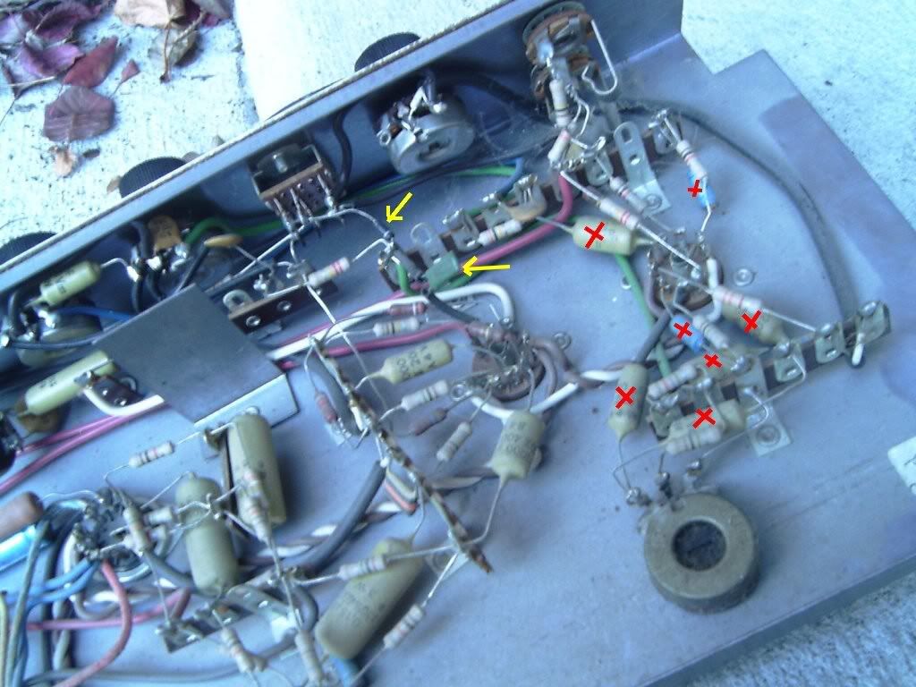
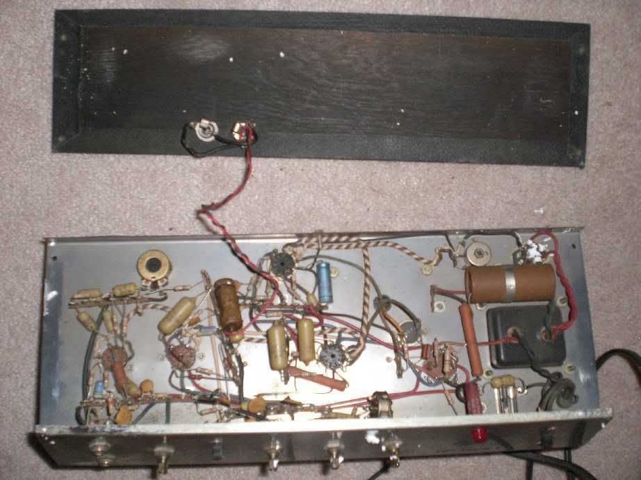
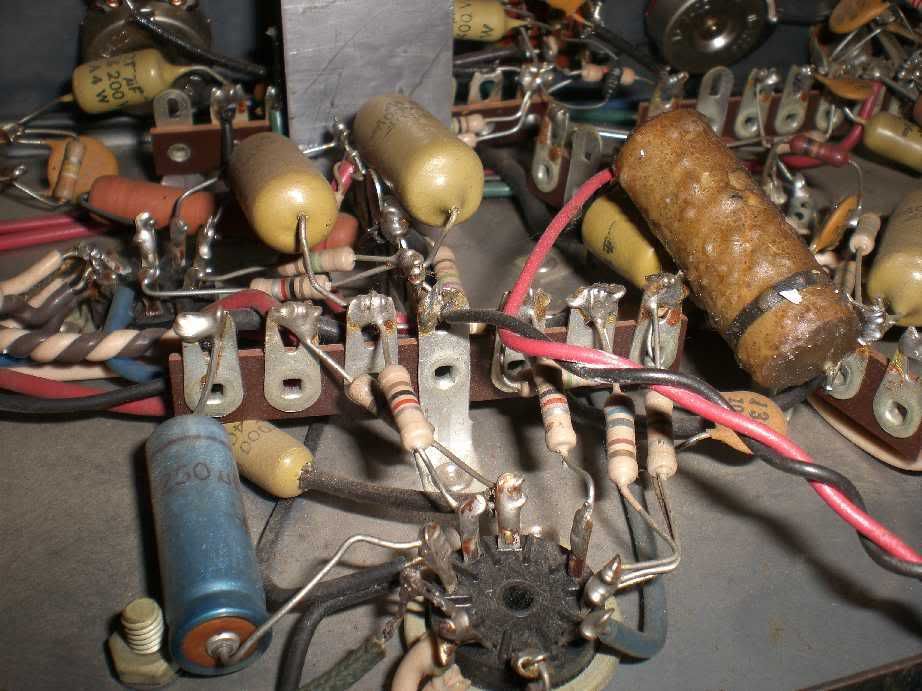
I replaced all the filter caps, rectifier tube, power tubes ( thanks again, coastie!) as well as the other caps but the ones that appeared to function solely for the tremolo circuit. Three prong cord, or course. I was going test voltages before firing it up with tubes, but I had one of those days at work that made me want to take a gamble and claim early victory. So far, I think I won.

I fired it up with the original power tubes in case I had trouble. A bit of crackling ensued, and I remembered having this issue with an old Champ 12, so I put in the new power tubes. No more crackle. At first the power light didn't come on, but lit up once the tubes were heated. I remembered someone mentioning this elsewhere on this forum. The tube cathodes had a nice orange glow and no funny smells. Plugged in a tele and hit a C chord. As every bit as bright as I've read..and that's what I wanted. The tremolo works too!

The only things I've noticed was a little bit of feedback when playing in front of her. It was very faint. It hasn't done it since. Could the original preamp tubes contribute to this? Also, I've had it pop when I turn it off. Not every time. Once rather low, and once rather loud. Could that be a resistor?

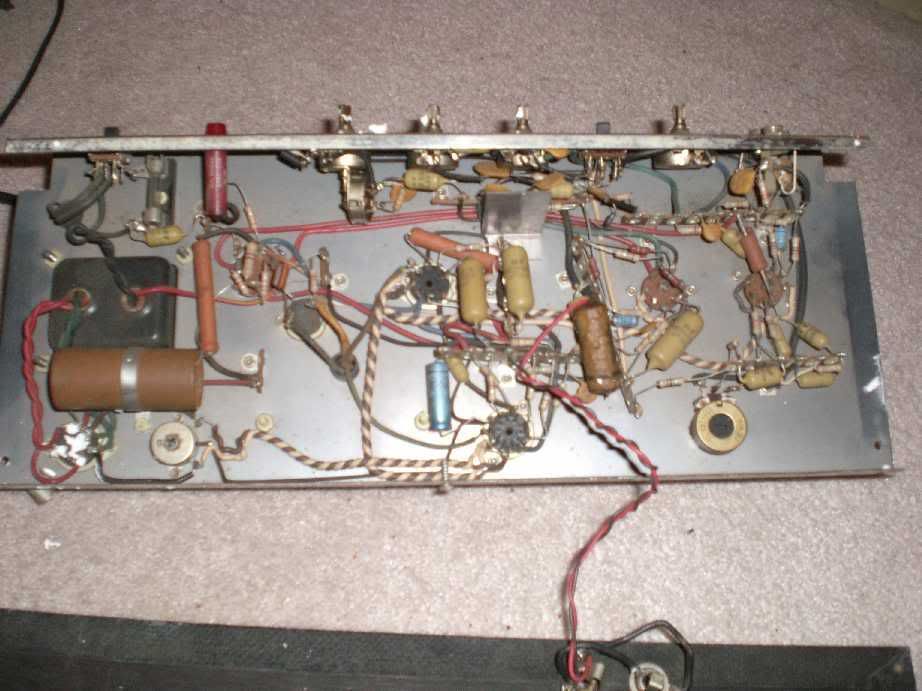
I can't get over how pretty it looks. I'll take some better pics. I'm going to plug my digiverb in front of it and break out the Jaguar. :wink:

Thanks so much for the help!!!

I'm going to invest in a new speaker next - probably a budget Weber. Opinions on Alnico vs Ceramic?
 

Default

Super Moderator
Platinum Supporting
Joined
Jul 30, 2007
Messages
13,648
Reaction score
3,075
Location
Philly, or thereabouts
Guild Total
11
Brendan said:
edit: This one looks like it would work ( at bottom of page)
http://www.mcmaster.com/ctlg/DisplCtlgP ... 5161595964

This?

7499kp1s.gif
 

capnjuan

Gone But Not Forgotten
Joined
Nov 29, 2006
Messages
12,952
Reaction score
4
Location
FL
Hi Brendan and congratulations ... not sure you've won but you seem to be ahead going into the fourth quarter. Some notes:

Trem caps: the two you should concern yourself with are the .15uf/400V appearing lower left on the schematic near V1B, the back half of the first 12AX7, and the 22uf/400V (22uf says the schematic). Since a 22uf/400V electrolytic cap there would be to big to fit, chances are it's supposed to be .22/400V. Both are drawn as electrolytic (straight and arched lines) but non-polarized polyester caps will work; that is, you do not have to observe polarity. These don't affect tone, they are worker bees, you want tough, not toneful here.
Crackling: chances are the tube pins and sockets were dirty. Get some non-lubricating contact cleaner, spray the socket and pins, and push/pull the tube in/out several times. Your old tubes will be good to go as backups and for comparing their differences with the newer ones.
Power light: In most amps, the light is powered off the 6.3VAC heater circuit - when the power is turned on, that winding is hot. In your amp, the lamp is DC and must wait for the tube rectifier to start conducting. The tube will only conduct after the heaters have warmed up. This isn't a problem, just not what your accustomed to.
Feedback: does it diminish if you move around the room? Feedback isn't normally tube-related.
Pop at turn-off: Not a resistor, not necessarily a big deal, is an annoyance, but could maybe be fixed with a 'pull-down' resistor from the B3 tap in the power supply to ground. See if it keeps up, maybe do some intervention.
Speaker: for this amp, ceramic ... my vote anyway.

Good going! CJ
 

Brendan

Junior Member
Joined
Nov 29, 2008
Messages
63
Reaction score
0
capnjuan said:
Hi Brendan and congratulations ... not sure you've won but you seem to be ahead going into the fourth quarter. Some notes:

Trem caps: the two you should concern yourself with are the .15uf/400V appearing lower left on the schematic near V1B, the back half of the first 12AX7, and the 22uf/400V (22uf says the schematic). Since a 22uf/400V electrolytic cap there would be to big to fit, chances are it's supposed to be .22/400V. Both are drawn as electrolytic (straight and arched lines) but non-polarized polyester caps will work; that is, you do not have to observe polarity. These don't affect tone, they are worker bees, you want tough, not toneful here.
Crackling: chances are the tube pins and sockets were dirty. Get some non-lubricating contact cleaner, spray the socket and pins, and push/pull the tube in/out several times. Your old tubes will be good to go as backups and for comparing their differences with the newer ones.
Power light: In most amps, the light is powered off the 6.3VAC heater circuit - when the power is turned on, that winding is hot. In your amp, the lamp is DC and must wait for the tube rectifier to start conducting. The tube will only conduct after the heaters have warmed up. This isn't a problem, just not what your accustomed to.
Feedback: does it diminish if you move around the room? Feedback isn't normally tube-related.
Pop at turn-off: Not a resistor, not necessarily a big deal, is an annoyance, but could maybe be fixed with a 'pull-down' resistor from the B3 tap in the power supply to ground. See if it keeps up, maybe do some intervention.
Speaker: for this amp, ceramic ... my vote anyway.

Good going! CJ

Thanks capn! I did replace all the .15uf caps with orange drops, but I didn't replace the .22uf. I'm going to remove the chassis and replace the remaining caps. I'll give the sockets a good cleaning too.

I had a chance to play it a while tonight and noticed that the problem wasn't really feedback..it was more of a low ring that didn't really increase and came on after playing a minute. Microphonic tube? When the ring isn't present, I can tap the tube in V1 and get the same ring. They are the original 12AX7 tubes, so I'll pick up a pair locally.

After posting last night, I hooked up the reverb pedal and the Jaguar. There was an odd static that seemed to have a crashing wave pattern to it. The tremolo wasn't working. I futzed around with different cables, removed the pedal and tried different guitars. Soon the problem stopped in the normal channel ( and tremolo worked), but the high gain channel still had the static and the tremolo wasn't working there either. No such problem tonight and I played for a long time. Odd.

I'll replace those tubes and the rest of the caps and see how it goes.
 

capnjuan

Gone But Not Forgotten
Joined
Nov 29, 2006
Messages
12,952
Reaction score
4
Location
FL
Brendan said:
Microphonic tube? When the ring isn't present, I can tap the tube in V1 and get the same ring. They are the original 12AX7 tubes, so I'll pick up a pair locally. You're on it. ... an odd static ... No such problem tonight and I played for a long time. Odd. Might could be the tube 1/2 that acts as the tremolo oscillator is about shot ... has some kind of intermittent in it or the switch contacts in the footswitch are dirty ... had a chance to take it apart yet?
CJ
 

Brendan

Junior Member
Joined
Nov 29, 2008
Messages
63
Reaction score
0
capnjuan said:
Brendan said:
Microphonic tube? When the ring isn't present, I can tap the tube in V1 and get the same ring. They are the original 12AX7 tubes, so I'll pick up a pair locally. You're on it. ... an odd static ... No such problem tonight and I played for a long time. Odd. Might could be the tube 1/2 that acts as the tremolo oscillator is about shot ... has some kind of intermittent in it or the switch contacts in the footswitch are dirty ... had a chance to take it apart yet?
CJ

Thanks capn. No footswitch on this one.

Antique Electronic Supply delivered the remaining caps and two JJ 12AX7 tubes today. Oooh, she sounds sweet. It's quiet at idle too. I adjusted the tremolo depth pot in back to get a bit more depth and I noticed that with the pot at about 3/4 to wide open, there's a slight "thump, thump, thump" that speeds up or slows down with movements of the speed knob. I backed the pot back to where that stopped and it sounds great. I wouldn't want any more depth anyway. It seems to be where the max should be. It's definitely a keeper. My only other amp is a Pro Jr with a Ragin' Cajun and this amp is a great alternative since I seem to have a preference for playing clean. The PJ is on the verge of breakup with the volume at 3...and that's with a 12AT7 in V1. :p I contemplated selling off the PJ and get my "grit" by picking up an old Gibson to tweak on, but I'm going to wait and see what happens with the job / economy before spending more. Well, maybe a Weber Signature for this one, then I'll stop. :D

I want to thank everyone for helping me out on this. I browse this forum daily and I feel very fortunate for finding such a great group of folks.
 

capnjuan

Gone But Not Forgotten
Joined
Nov 29, 2006
Messages
12,952
Reaction score
4
Location
FL
Hi Brendan; I guess that's the depth pot on the back - not shown on the schematic, only speed. My only suggestion would be if/when you need or want to get back in there, that you replace everything in tremolo circuit that you haven't done so far; it shouldn't thump even at full on. $3 in parts and an hour of your time and you'd have it as good / better than new. Congratulations! CJ
 

Brendan

Junior Member
Joined
Nov 29, 2008
Messages
63
Reaction score
0
capnjuan said:
Hi Brendan; I guess that's the depth pot on the back - not shown o n the schematic, only speed. My only suggestion would be if/when you need or want to get back in there, that you replace everything in tremolo circuit that you haven't done so far; it shouldn't thump even at full on. $3 in parts and an hour of your time and you'd have it as good / better than new. Congratulations! CJ


Hi capn. I did replace all the electrolytics around V1 that seemed to be associated with the tremolo and I'm still getting a thump. All the resistors tested fine. I've been searching online for possible solutions and understand that I have a bias modulating tremolo circuit. One solution I have seen posted for a Bandmaster with the identical issue stated, "I would suspect the capacitor coupling the LFO to the bias point.", so I'm looking at pin 3 on V1 since I did change all these caps.

I was looking at the circuit tonight and noticed an odd connection to V2 that I don't see on the schematic. Here's a recycled pic - I put a red X on caps I have since replaced - but what do you think of those two items marked with yellow arrows? One very small component comes off one of the top lugs of the tremolo switch (not sure what this component is), then joins with a very small green cap (with shielded leads) and connects to pin 2 on V2. Any thoughts on that? I'm not sure it's relevant to this issue, but thought I would throw it out there in case I'm wrong..

Trem-1.jpg
 

capnjuan

Gone But Not Forgotten
Joined
Nov 29, 2006
Messages
12,952
Reaction score
4
Location
FL
Brendan said:
... I did replace all the electrolytics around V1 that seemed to be associated with the tremolo and I'm still getting a thump.
Hi Brendan ... hmmm .... we doesn't care for thump .. :evil:
Brendan said:
One solution I have seen posted for a Bandmaster with the identical issue stated, "I would suspect the capacitor coupling the LFO to the bias point.", so I'm looking at pin 3 on V1 since I did change all these caps.
eh ... LFO? Not sure, but V1/pin 3 on a Bandmaster is the cathode of the first stage commonly bypassed with a 25-50uf/25V electrolytic that contributes to the tube's bias .... I don't think it relates to your amp.
Brendan said:
... an odd connection to V2 ... One ... component comes off one of the top lugs of the tremolo switch ... then joins with a very small green cap (with shielded leads) and connects to pin 2 on V2.
I guess Guild is as guilty as Gibson for undocumented on-the-fly changes .... Please confirm that at V2/pin 2, there are three connections; 100K resistor, .03 coupling cap, and the alien green cap. If the mystery thing has no markings or color coding typical of resistors and older capacitors and has only a white or silver band on it, then it's a diode. You can confirm this with either a VOM or continuity tester. If it's a diode, it will show 0 resistance in one direction and infinite resistance in the other.

If it's a diode (green triangle below), I think this is what you have ... and my suggestion addressing thump is to replace the cap; consider a one step increase in value and be certain that it's rated for 600V (it should not be a 400V girlie-man capacitor... :evil: :wink: ) While you're at it, you might as well replace the diode; IN4007 ... put in a big boy, don't wait for the one you have to fail. Unless one end is grounded, that isn't shielding on the legs of the caps; just tubing to prevent contact with any other component leads; save and re-use it or replace it.

brendansbias.jpg


Whatzit doing there? I think this amp causes tremolo by modulating the grid voltage at V2/pin 2 where modulate = fluctuate. The only other possibility is guaranteeing that the voltage on the V2A grid, pin 2, stays negative with respect to the V2A/pin 3 cathode.

Lecture ensues; (no quiz but if you're caught asking the same question again, I will see to it that Graham makes fun of you :wink: ) For any audio tube to conduct and amplify, the grid voltage must be lower or more negative than the cathode. In cathode-biased amps, this voltage differential is done by tying the output tubes' cathodes together, connecting a resistor, and connecting the resistor to ground. This causes a voltage to appear inside the tube on the cathode and based on the value of the resistor - commonly 200-470 ohms - the voltage on the grid (because we just got through forcing one on the cathode) is lower than the cathode.

By contrast, your amp is 'fixed bias'; there is no output tube cathode resistor to induce the critical voltage differential relationship between the grid and the cathode. The required voltage differential is 'forced' by injecting a small negative voltage on the output tubes' grids - in you amp through the 390K dropping resistors. That way, the voltage appearing on the grid is always negative ... that is ... it's more negative than the cathode which is the desired condition. Before leaving the subject, that's why at least one half of a preamp tube - commonly both - have a cathode resistor to ground; the preamp tubes are cathode-biased like output tubes in cathode-biased amps; the cathode resistors force a voltage on the cathode guaranteeing that they are more positive / less negative than their grids.

In your amp and for the tremolo, you have to manipulate grid voltage somewhere; in older amps it's at the output tubes; in your amp, it looks like it's at V2A/pin 2. When the tremolo is on, there's positive voltage circulating through V1B - the oscillator circuit. V2A/pin 2 is connected to the source of the oscillation by the diode so that when V1B does its thing, the diode prevents either the + or the - DC voltage from appearing on V2A/2 and the grid voltage fluctuates causing the owaowaowaowa ...

If this is wrong, then the diode/cap leg from the trem switch is intended to force a negative voltage on V2A/2 by blocking the + DC and works irrespective of the on/off condition of the trem switch ... and the owaowaowaowa is in fact done via the 390K dropping resistors. If you're curious about which, then disconnect the cap at V2A/2; if the amp works ok but no trem, then it's door number 1, the bias relationship of V2A is the source of your trem. If you get squeally, ugly, nasty out, then the diode/cap is for V2A bias setting only. Good luck with your amp! CJ
 

Brendan

Junior Member
Joined
Nov 29, 2008
Messages
63
Reaction score
0
Thanks capn! V2, pin 2 only has two connections: the 100K resistor and the alien cap marked, ".0047 K100v". The .03 coupling cap is connected to pin 7. The mystery thing only has one white band. I tested it with an ohmmeter and got infinity in both directions. Hmmm.

With the diode apparently shorted, I'll buy a replacement ( much thanks for the part #) and install a manly cap to replace that green one. Then I'll see what she does.

I noticed that the tremolo switch doesn't engage about 25% of the time. Time to find another. A 9 lug on/off slide switch is a rare beast, but I'll keep looking.

My amp had another deviation from that schematic. The power tubes are cathode bias too.
Thanks for the explanation. I absorbed half of it at first read and will read it again and follow it on the schematic. Even though the schematic is for a fixed bias version, I really want to understand how it works.

I appreciate the help!
 

capnjuan

Gone But Not Forgotten
Joined
Nov 29, 2006
Messages
12,952
Reaction score
4
Location
FL
Brendan said:
V2, pin 2 only has two connections: the 100K resistor and the alien cap marked, ".0047 K100v". The .03 coupling cap is connected to pin 7. Hi Brendan; see below - I noticed that the tremolo switch doesn't engage about 25% of the time. Have you tried soaking it with contact cleaner and pushing it back and forth a few times? My amp had another deviation from that schematic. The power tubes are cathode bias too. Hmmm ... see quotation below ..
V2A/2: if there's only the 100K resistor and the alien cap, since the resistor is tied to V2A's cathode (pin 3), the signal into V2A has to be via the alien. Whether the signal is fed through the diode or by the 22K resistor tied to it at the wiring strip doesn't really matter because ... as the poet said: "Ain't it just like the night to play tricks when you're tryin' to be so quiet ..." Visions of Johanna, Bob Dylan The schematic can't be relied on to map out how it's wired. If we assume that it once worked correctly as-wired, then it's a reasonably safe assumption that the reason it doesn't work now is because a component has gone south ... or ... the poor alignment of Venus and Jupiter in Sagittarius.

Re pic below; confirm no contact between the component leads shown. Also, don't forget to clean that ureachable-when-playing pot at the lower right. (Untrustworthy) schematic shows only one trem control; 'speed' - is there another somewhere? On the control panel? How does the amp vary 'depth' ... if at all? Please confirm.

BrendansT1treme.jpg


Full speed ahead on the diode and the alien cap. CJ
 

Brendan

Junior Member
Joined
Nov 29, 2008
Messages
63
Reaction score
0
I just gave the switch and the lonesome pot a good shot of contact cleaner. That pot is the depth control. I verified there was no contact with that resistor lead in the pic above and I looked over all other connections to make sure nothing was touching where it wasn't supposed to. I did notice that the red wire on pin 1, V2 was soldered to the side of that pin by the factory which put it rather close to some excess solder at pin 2. It may not have been an issue, but I cleaned that up. I verified that all my soldering was solid. All connections are shiny.

I tried to buy a 1N007 diode and even though I've seen other references to it on the 'net, a local electronic shop with a wall of diodes had none and couldn't find it in their system. I wanted to try something else, but had no idea where to start there. That place is a bit overwhelming. I stopped by Radio Shack and found a 1.5A, 1000v rectifier diode and a .0047 500v cap. That's all they had for caps ( forgot to grab one at the other place. I really dislike RS) I figured it suited the purpose. I installed these last night and they seem to work fine, but no real change with the tremolo.

I'm going to button it up now and see if there's any difference with the clean pot. I'm crossing my fingers. Much appreciated, capn!

Here's an aerial view with my quirky camera.
Thumpy.jpg
 

capnjuan

Gone But Not Forgotten
Joined
Nov 29, 2006
Messages
12,952
Reaction score
4
Location
FL
Well? <he said with bated breath> ... did it work? The diode reference was IN4007 ... but you did good anyway. The part's 1.5A / 1000V rating will help prolong its useful life. Nobody should be surprised that Guild and nearly everyone else bought the least-cost part that would do what they wanted. Don't know the rating of the old one but the price difference in up-rating in this context is peanuts and you get the satisfaction of knowing that, going forward, you leave behind a path of new, stronger parts that will contribute to tone and longevity. CJ
 

Brendan

Junior Member
Joined
Nov 29, 2008
Messages
63
Reaction score
0
capnjuan said:
Well? <he said with bated breath> ... did it work? The diode reference was IN4007 ... but you did good anyway. The part's 1.5A / 1000V rating will help prolong its useful life. Nobody should be surprised that Guild and nearly everyone else bought the least-cost part that would do what they wanted. Don't know the rating of the old one but the price difference in up-rating in this context is peanuts and you get the satisfaction of knowing that, going forward, you leave behind a path of new, stronger parts that will contribute to tone and longevity. CJ

Hi capn,
It seems to be about the same. I have a fair selection of linear and audio taper pots here, so I thought I would replace the depth pot and use a knob on it since I'm tired of fumbling with a screwdriver during this exercise. It turns out that's a 1 meg linear taper pot. That surprised me. I Googled for tremolo depth pots prior to removing and didn't see other designs using ones that big. I do have a new 1M linear pot, but realized I would have to drill the chassis out, so I left it alone. The pot has even motion and is behaving correctly according to my ohmmeter. The switch, on the other hand, took a few movements to get it to work last night. It's fine today, but I paid another visit to the dimly-lit electronic store to see if I could find a replacement. They only had toggles, but when I told the guy what it was for, he knew of these amps! He found a switch on ebay for me. Not sure how I missed that, but here's the auction:
http://cgi.ebay.com/CW-GF-661-SLIDE-SWI ... tches_Wire

The mounting holes are too far apart, but I have a good assortment of taps and I'm sure I can trim the ears, re-drill and make it fit. Ha! Now my trem switch will match my power switch.

I'll see how it behaves after I install this. If no improvement, I think I'm going back to the step I skipped earlier - fire up the chassis on the bench and get some readings to make sure everything else is up to spec. While I wait for the switch to arrive, I'll do some reading to figure out what kind of readings I should expect. I've never done that and I need to learn ( safely). If all is fine there, I might make one last round of replacements of the tremolo caps - the new yellow ones were the cheapies. I did notice that the 25uf black sprague cap leading to pin 3, V1 is tied in to this circuit. That was a 32 uf cap originally, but no direct replacements were available. Any chance that difference could be contributing to the issue?

Much appreciated!
 

capnjuan

Gone But Not Forgotten
Joined
Nov 29, 2006
Messages
12,952
Reaction score
4
Location
FL
Brendan said:
I did notice that the 25uf black sprague cap leading to pin 3, V1 is tied in to this circuit. That was a 32 uf cap originally, but no direct replacements were available. Any chance that difference could be contributing to the issue?
Hi Brendan; that's the cathode resistor bypass cap. The cap's function is part tube bias and part shaping of the amp's frequency response. The 7 uf spread between original and new wouldn't have any bearing on go/no-go for the trem. Even if it was bad, it still wouldn't have any influence on go/no-go. Slide switch looks good; make sure to draw a sketch of all the existing connections and confirm the orientation of the switch. I hope you can make it work because that style slide switch isn't commonly supported. CJ
 

Brendan

Junior Member
Joined
Nov 29, 2008
Messages
63
Reaction score
0
I got the switch in and it works perfectly. It turns out that the auction was for four of them. I thought he was listing four as available. Now I have spares and could use one for the power switch if need be. No difference on the tremolo. The bench test is next, but I'm still sufficiently creeped out about using a voltmeter on a live amp. I'll be careful.

I'm going to order up a 12" Eminence Cannabis Rex for this one. It has a ceramic magnet, late breakup and some excellent owner testimonials on several forums - boost the bottom end and take a little bit of the icepick off the top. My three guitars - Esquire, Dano and Jaguar - are all on the bright side and I think this speaker will fit the bill. Samedaymusic has them for $80 shipped which is only $10 or so more than the Weber equivalent after shipping factors in.
 

capnjuan

Gone But Not Forgotten
Joined
Nov 29, 2006
Messages
12,952
Reaction score
4
Location
FL
Hi Brendan; Remember when hot-checking to set your VOM correctly; when checking DC voltages, the VOM acts like a load that prevents DC shorts to ground. Getting a Dummy Load will satisfy the need to have a resistive load across the output transformer's secondary if you prefer to disconnect the speaker to prevent clicks and pops ... which can make you flinch pretty good :wink: . I can't remember whether you said you had already subbed-in a known good 12AX7 in V1; if not ...

As long as your'e at it; you need to hot-check that 220K dropping resistor at V1B (the resistor might not match the schematic but it will have it's own color code) If it's beige carbon film type, you can expect 5%-10% variance between what it measures and what it's supposed to be. Whatever it is, it 's seeing 300V on the supply side; enough to shorten the life of a 1/2 watt resistor:

BrendansT1tremf.jpg


Goo luck! CJ
 
Joined
Feb 17, 2009
Messages
9
Reaction score
0
Location
Erie, PA
Hi! I'm Mike. Quick background on me. Been playing guitar off and on (more off it seems) for the last 22 years. I've built two homebrew tube amps. One based on the AX84 high octane, and a second one based on the Marshall 18W lite. I've customized both of those with some bias schemes as tonal tweaks to my liking.

One of my buddies has an older Guild Thunder 1 that he wants me to get working again, and perhaps do a few mods to it, which brings me to this thread. It's the two input version without reverb. Capnjuan was kind enough to email the T1-12 schematic, which is close, but not quite what I have. I also received some schematics from Don. Thanks to both of you! Prior to that, I was sketching the circuits out by reading color codes and lots of wire tracing. While that's sometimes fun, it was getting tiring this round.

From my initial visual on the amp, I could see it was clearly modified in the past. I ended up drawing the schematic that matches what I have using ExpressSCH and saved it as a pdf as well as a jpg, so that I could post it on photobucket.

GuildThunder1sheet1.jpg


GuildThunder1sheet2.jpg


The original issue with the amp was loud hum and buzz. I'll be redoing the power section caps, as well as most of the other caps in the amp, due to the age. The owner wants a little less brightness as well as add some more gain to it. Any suggestions on that would be welcome.

Well, here's the amp (chassis)
guildguts1.jpg


guildguts2.jpg


guildguts3.jpg


guildguts4.jpg


guildguts5.jpg


Anyways, I'm hoping to enjoy the forum and your knowledge.
 
Top