Wiring Schematic for a Build

GSFV

Member
Joined
Jan 3, 2018
Messages
204
Reaction score
57
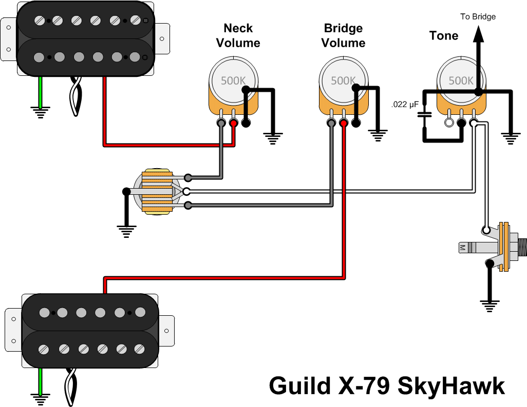
Not quite Guild specific, but It is inspired by my Starfire V. I love blending the neck and bridge volume knobs, but I also find that I ride the master volume knob A LOT. I've got another guitar that has a Humbucker Sized P90 in the Neck, and a Humbucker in the Bridge, along with three knobs. Originally I wired Neck Volume, Bridge Volume with coil split, Master Tone. But that doesn't allow me to do Master Volume, and I'm really missing it as an option.

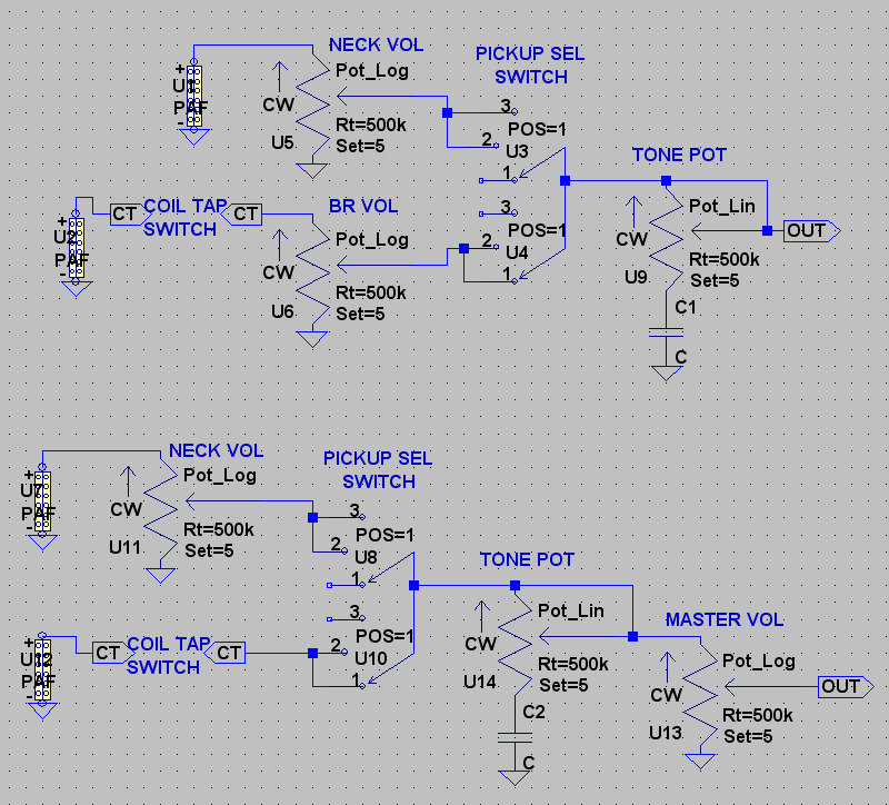
Would it be possible to wire a Master Volume, a Neck Volume, and a Master Tone? I'm trying to figure this out, but I'm struggling. Icing on the cake if you can also split the bridge humbucker somehow.

I was think about just taking the neck wire, and soldering two jumper wires from it; one to the NV, one to the MV.


Any help would be great! Thanks guys!
 

Dix_

Junior Member
Joined
Apr 22, 2019
Messages
12
Reaction score
3
Location
An ice station bunker in the mountain wilderness o
It's actually easier than you're thinking.

The coil tap should really be nothing more than a switching circuit (which looks an awful lot like a pickup selector switch) added onto the back of the bridge pickup's volume pot. (or the back of whatever pot is doing the switching)

1. Find the output of that switch, which should be connected to one of the legs of the bridge volume pot. Break the circuit at that point.

2. The pot's output or "wiper" should be connected to the pickup selector switch, Break that connection as well. You have now removed the bridge pickup volume pot from the circuit.

3. Connect the coil tap switch output that you disconnected in step 1, to the pickup selector switch where the volume pot used to be.

4. Now go to where the tone control connects to the output jack. Break that connection. Connect the tone control output to the input (leg) of the volume pot, & connect the output (wiper) to the output jack.

Done.

It may help to think of the controls in a passive pickup circuit as nothing more than building blocks, you can put 'em anywhere you want for any configuration, so long as the pickup is the 1st thing in the chain, & the output jack is the last one it's all good.... well... don't forget to make sure all the grounds are connected together (usually on the back of one of the pots).

Assuming that the top diagram is your current wiring, the bottom diagram is the mod.

master_vol.png


As an aside, if you find that the bridge pickup is now a bit overbearing, just wire a 500k resistor between where the volume pot used to be and ground. That'll lower it's output a tad.
 
Last edited:

GSFV

Member
Joined
Jan 3, 2018
Messages
204
Reaction score
57
Wow!! That is very descriptive and helpful. Thank you! I think that the top one is pretty similar to what I've got. I was worried I'd done something wrong because I've never seen a tone pot lead to the output jack. Glad to know that that isn't the case.

Thanks again! This is very helpful!! Hopefully it wasn't terribly difficult to put together.
 

Dix_

Junior Member
Joined
Apr 22, 2019
Messages
12
Reaction score
3
Location
An ice station bunker in the mountain wilderness o
No problem.

The schematics are just a screen grab from a simulation program I use called LTspice. So they're easy enough to generate. Just drop components onto the grid & draw the connections.

2 volumes & a master tone isn't an unusual circuit. Gibson's Flying V & Explorer are probably the 2 most famous examples. The tone would have to be the last thing in the chain since it needs to be always active regardless of pickup selection.

If I can borrow a diagram from Gary... Guild's X-79 also shares that circuit.

Guild-X79-Skyhawk-Wiring.png


You may notice that circuit and my diagrams above are slightly different connections-wise but they work exactly the same.

The wiper and the clockwise leg of a volume pot are interchangeable. Either can be the input/output, functionally there's no difference in either way you wire it. Just remember that the counter-clockwise leg needs to connect to ground. Heck, you can connect the wiper to ground if you use the counter-clockwise leg as the signal in/out.

Same deal for a tone control. The first two diagrams below are the way you usually see 'em connected. But, the last one works too (the way it's done in the X-79 diagram). Just notice that counter-clockwise is "up" in that case.

tone.png
 
Top