Replaced electrolytic caps and cord.
Extension for highvoltage leads from pt. The go to a Fender double pole, single throw standby switch. Due to the voltage-doubling circuit, I needed a dpst to interrupt the ac before it was rectified. Unfortunately, the switch was rather bulky and I had limited room. If I had used a smaller spst switch after the rectifier, it would have resulted in a high, no-load voltage on the first set of 250 mfd caps. Stacked, They're good for a thousand volts, but this beast had 530 volts on the plates of the 8417s. The black caps are the bias caps. Not pictured is the cap for the screen voltage. On the schemo, it looked like a 20 mfd cap was called for. In this amp, a 2 mfd was actually in place. I replaced that with a 4.7 mfd cap.
"Driving sideways"
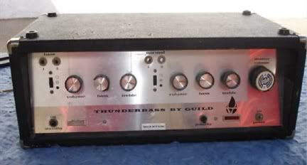
Standby switch by the cord. Hum balance is adjusted by the mark 1 ear. Just turn it back and forth until you reach the position of least hum. The big tubes are 8417s - like a 6l6, but on steroids. They were one of the last tubes to be designed, therefore one of the hardest to get. In fact, I was not able to get a matched set. Guild, however, designed this amp with a bias pot for each tube, meaning that you can adjust each tube's bias easily with a voltmeter and a screwdriver. You can see the round test probe jack at the top.
In front of the powertubes, the 7247 phase inverter tube plugs into the pc board. A white wire provides negative feedback voltage from the speaker jack. Negative feedback reduces distortion (and volume) not that volume should be an issue.
In front of that is another pc board holding a 12ax7. The master volume pot is so close that a signal lead was shorting out on the tube shield, creating a nasty buzz until I rotated the pot out of harms way.
According to the USPS, delivery was attempted today, and why would they lie to me? :roll: