mellowgerman said:
hmm what exactly do you mean by "dime it"? also, should the standby light be on or off when hooked up to the remote amp?
Hi MG; 'dime it' means turn the volume all the way up to ten. As far as the standby switches are concerned - yours and the remote amp's, you'll just have to experiment. So long as you keep the volume down, you can't screw anything up.
Below left: Guild 2-tube pre-amp Thunderbass shown. In normal operation, the signal follows the dark blue line and it appears on the output jack but doesn't go anywhere. It loops up the input jack, through the contact arm, and back down. If a remote signal were jacked in, the plug would open the contact arm breaking the normal circuit and the amp-in signal would follow the light blue line. The red dot is the junction of the standby switch (in green circle) and the line signal. If the standby switch is in the On Standby position, the output of the preamp is grounded out but the power section is still running and it can process a remote signal. So long as the standby switch is On Standby, this amp cannot have it's ouput section overloaded with both local and remote signals. If the standby switch is in the 'On' position, this circuit relies on the Amp-In jack to break the normal ciruit.

In the amp on the right, a Guild 3-tube preamp Thunderbass head. The standby switch (green circle) is downstream from the Out/In jacks. In normal operation, the signal follows the dark blue line; up the 'amp in' jack, across the contact arm, and reaches the input (grid) of V2B. At that point, if there is a load connected at the Out jack, the signal flows through V2B and appears on the output jack. Since nothing is normally connected there, the signal bypasses V2B and continues in the circuit reaching the red dot; junction of the line and standby switch. If the standby switch is in the On Standby position, it will ground out everything; the normal local signal or a jacked-in remote signal. The contact arm on the 'amp in' jack disconnects the local signal and the remote signal bypasses V2B. When the standby switch is downstream of the Out/In jacks, the standby switch must be in the 'On' position if it's going to pump out a signal; its own or remote signal.
As indicated, the On Standby/On positions of the standby switch to export/import signals is governed by the type of jacks and the location of the standby switch in the circuit and as far as matsickma's experiments are concerned, we are overlooking the manufacturer's Yin and Yang here. There's a normal tendency to assume that what's on the schematic matches what's in the amp and that whatever's there is wired correctly and isn't burfed up.
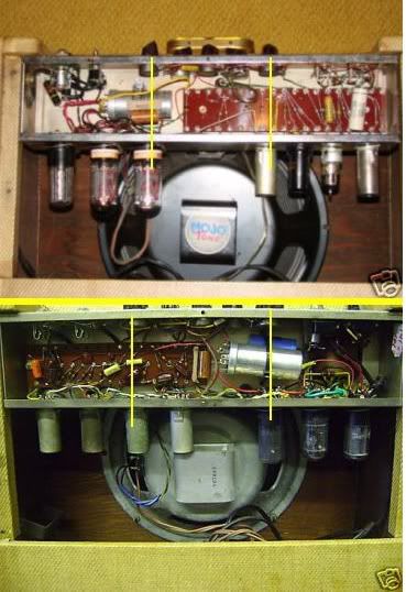
At the risk of grinding my Gibson axe to make this point; in the pic below, the amp on top is a late 50s/early 60s Gibson GA20T (I own one like it). The amp on the bottom is a late 50s/early 60s Gibson GA20T ( I own the amp on the bottom of the pic ... dang you Mad Dog :evil: :lol: ). You'll note that in the amp on top, the output and rectifier tubes are on the left and the circuit board is on the right. On the bottom, the output and rectifier tubes are on the right and the circuit board is on the left ... and you get extra credit if you noticed that the circuit board on the bottom is populated by a lot of lumpy things - capacitors - while you can only see two capacitors on the circuit board on the top (the 'loop' is the footswitch cord) ....... the capacitors are on the bottom side. Finally, the preamp tubes in the upper amp match the schematic, the ones in the lower amp do not ... although the amp works.
My point is that just because a schematic says something, it doesn't necessarily mean that that's how the amp is built or that, however it's built, it works correctly. Watch the volume and don't wet the power cord before putting it in your ear. Best, CJ

