Capacitor/wiring questions on 1954 M-75

BradHK

Senior Member
Joined
Jul 1, 2014
Messages
1,063
Reaction score
2,749
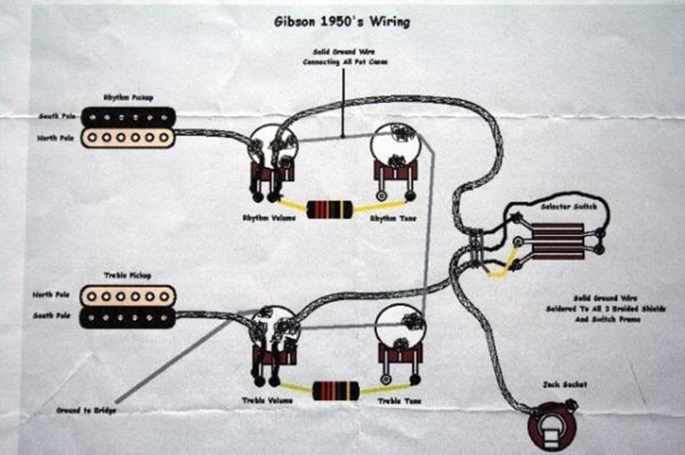
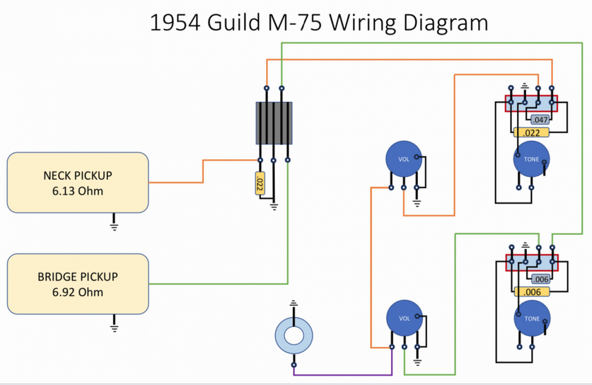
I am going through the wiring of my 1954 M-75 Aristocrat and have a couple questions that somebody with a more extensive knowledge of guitar wiring hopefully can answer. From what I can tell, everything is original from 1954. I have drawn out a wiring diagram but need to take my hand drawn diagram and put it into an electric format. Any software packages or website tools for this? The general routing of the wiring is that the wiring from the pickups goes first to the three way selector switch, then to the tone pots, then to the volume pots and then to the output jack. My main question is around the use of caps.

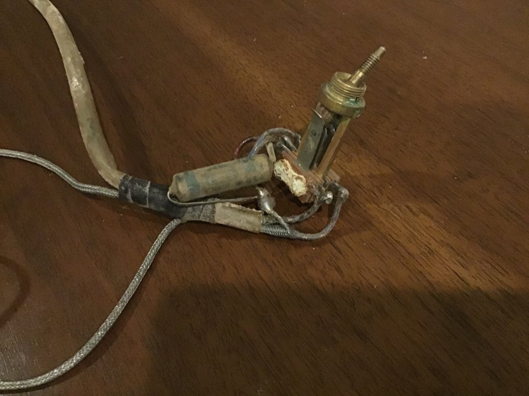
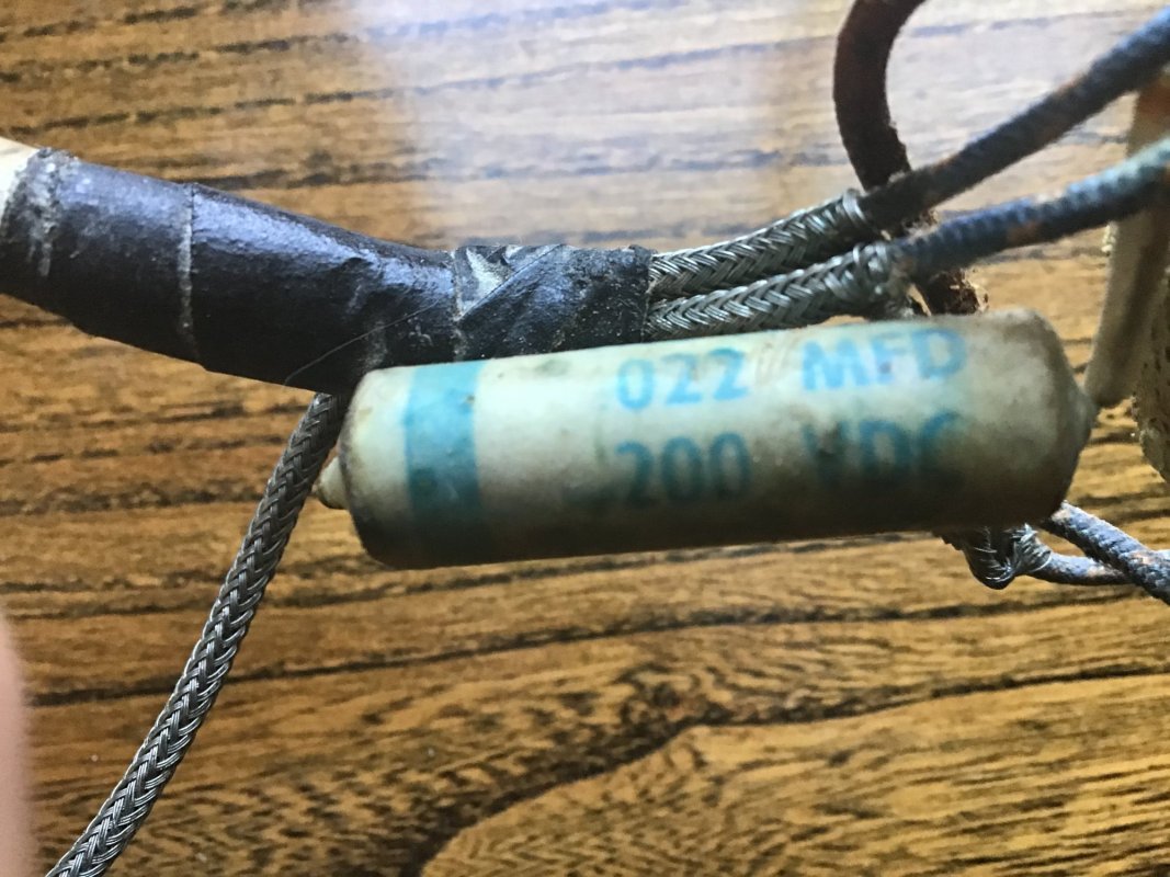
The first question is that there is a 002 MFD cap at the three way selector switch between the bridge pickup lug and the ground lug. I would guess this would darken the tone of this pickup all of the time. Is that correct?

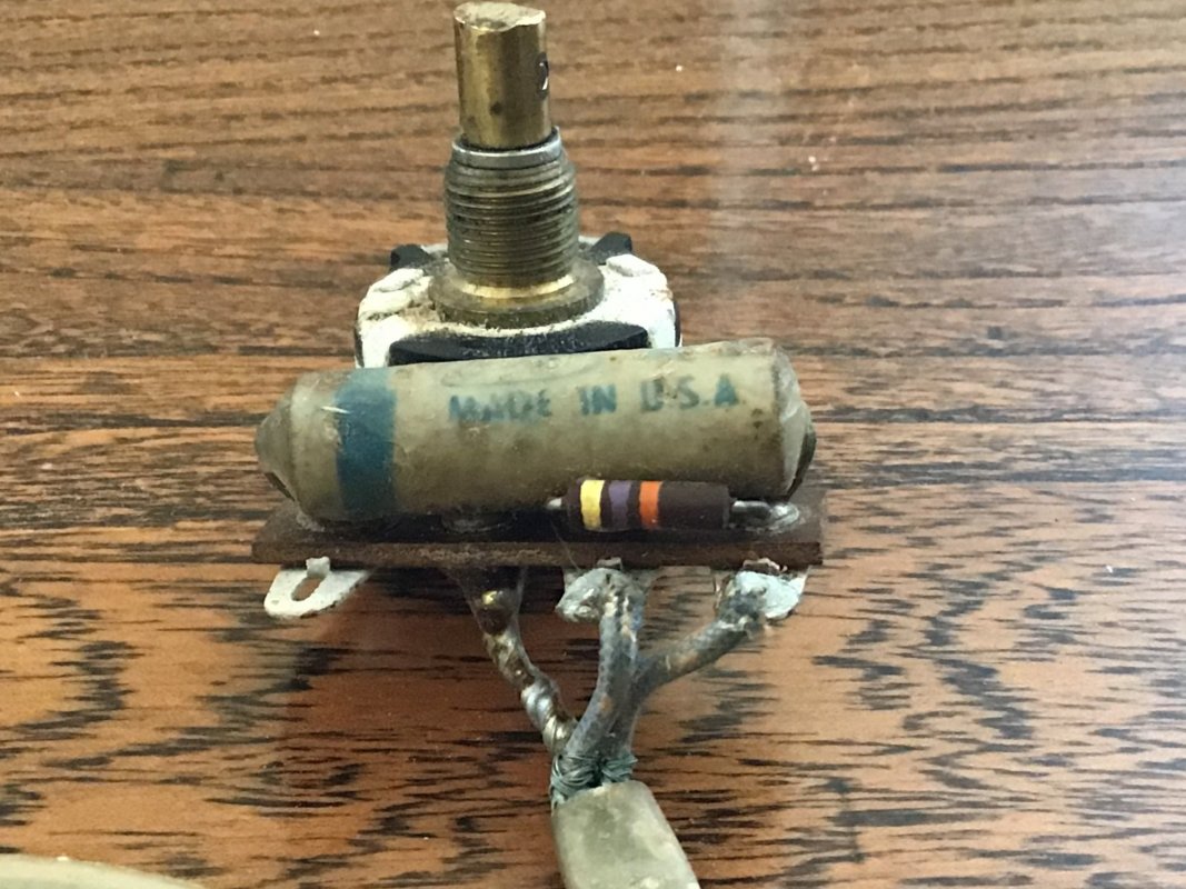
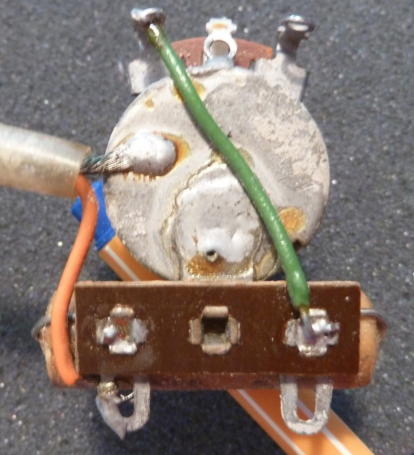
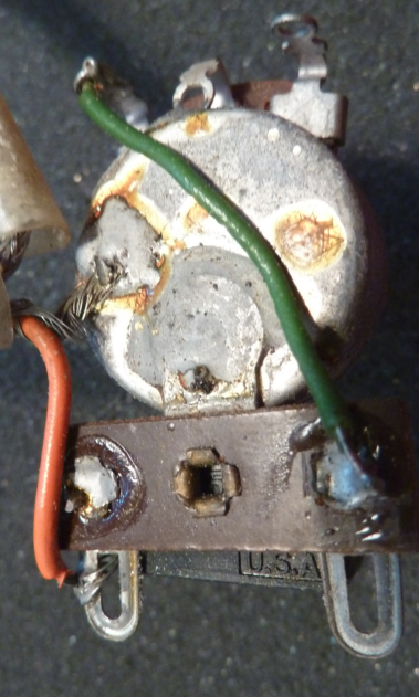
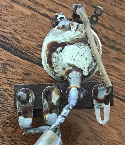
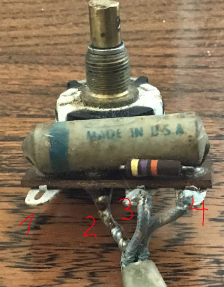
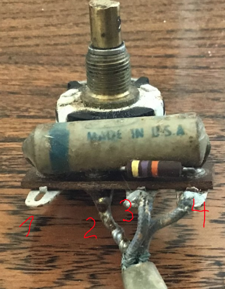
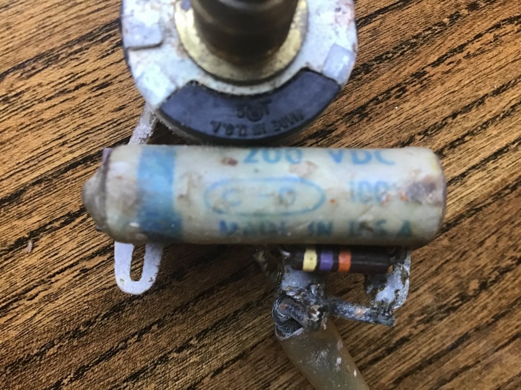
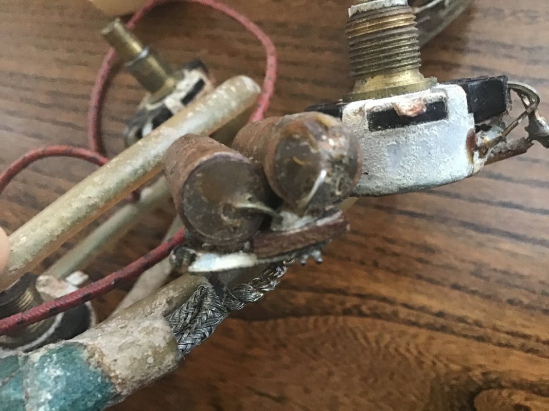
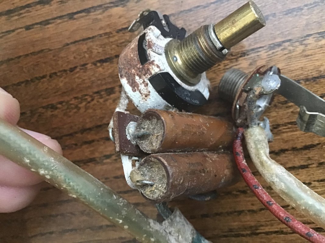
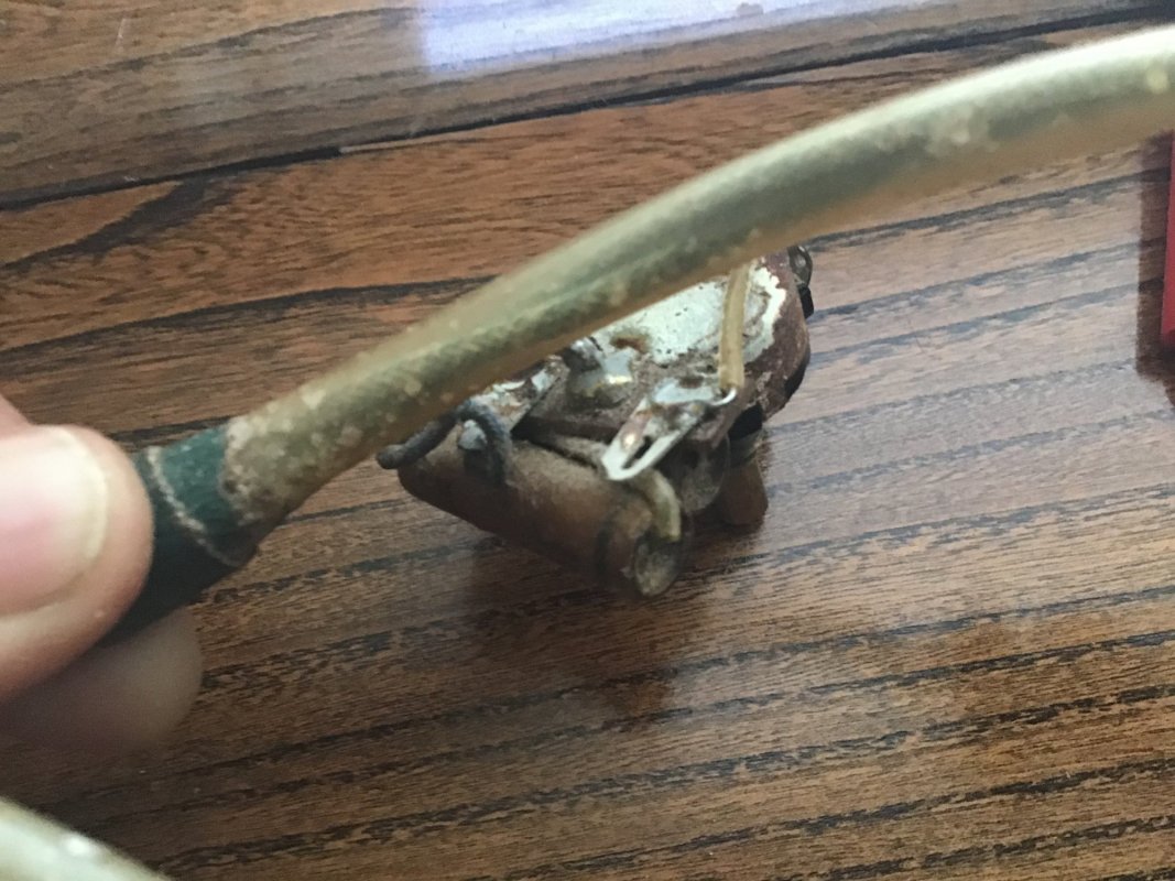
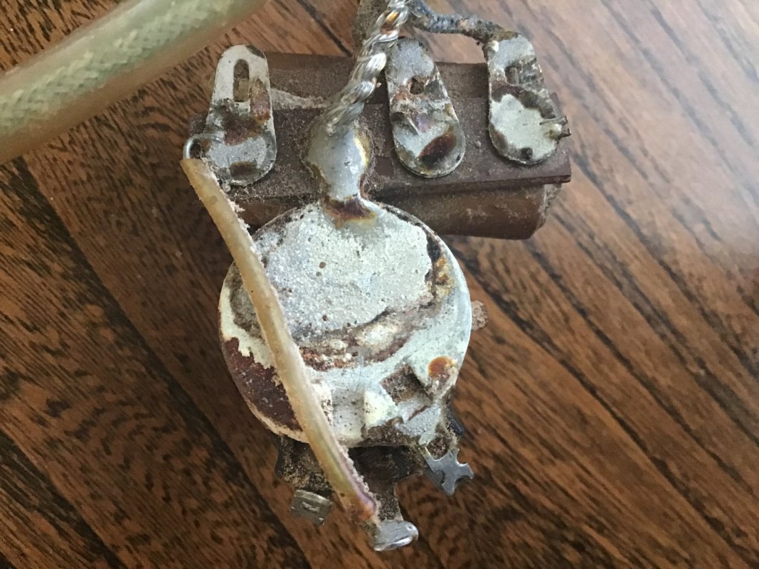
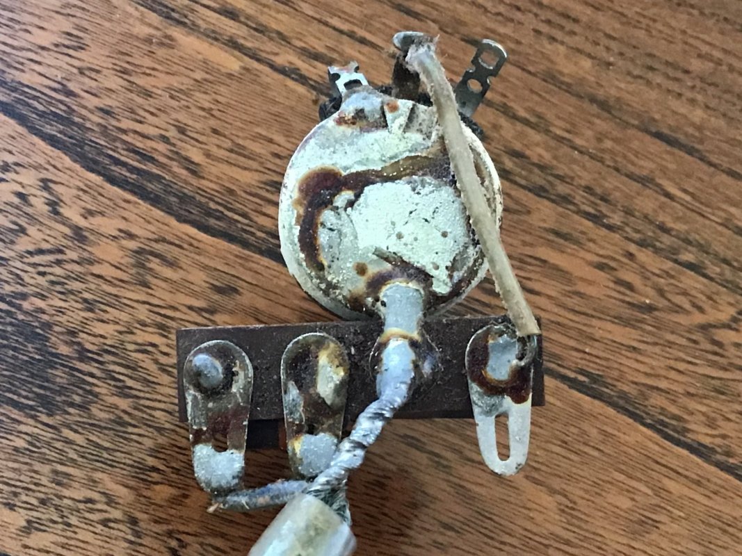
My second question is around the use of caps at the tone pots. The signal from the selector switch goes to a four lug circuit board beside the tone pot (Pictures below). The pickup signal goes to the far left lug in the photo of the pot from the back. In addition to the pickup lead there are two caps attached to this lug. A 022 MFD cap is wired between this left lug and the far right lug then goes to the tone pot center lug. This part (other than the circuit board use) is normal to me and the tone pot controls the use of this cap. The lug on the circuit board second to the right is just a ground. The lug on the circuit board second to the left is the signal going to the volume pot then to the output jack. This Circuit board lug is connected to the far lug on the left (pickup signal from the selector switch) by a cap. That would mean that all of my pickup signal is going through a cap. This was verified by a multimeter. The use of a cap to send the full pickup signal through (rather than bleed off high frequencies to ground) is new to me. Has anybody seen this before? Any thoughts?

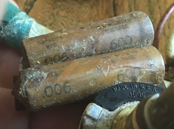
The last question is whether anybody can identify the brand and size of the small brown cap in my photo with the yellow, purple and orange bands. I know the bands represent the value but I have not been able to locate a reference sheet for this brand cap.

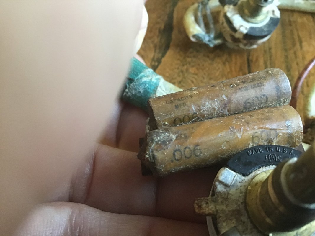
The tone pot in the photo below is for the bridge pickup. The neck pickup does not have a cap at the selector switch, it is wired with two caps and the circuit board just like the bridge pickup but both of the caps for the neck pickup are 006 MFD. Based upon the use of caps it appears that this would make the bridge pickup darker than the neck. That seems backwards to me. I am unable to read the pot values so these could be different for the neck and bridge.

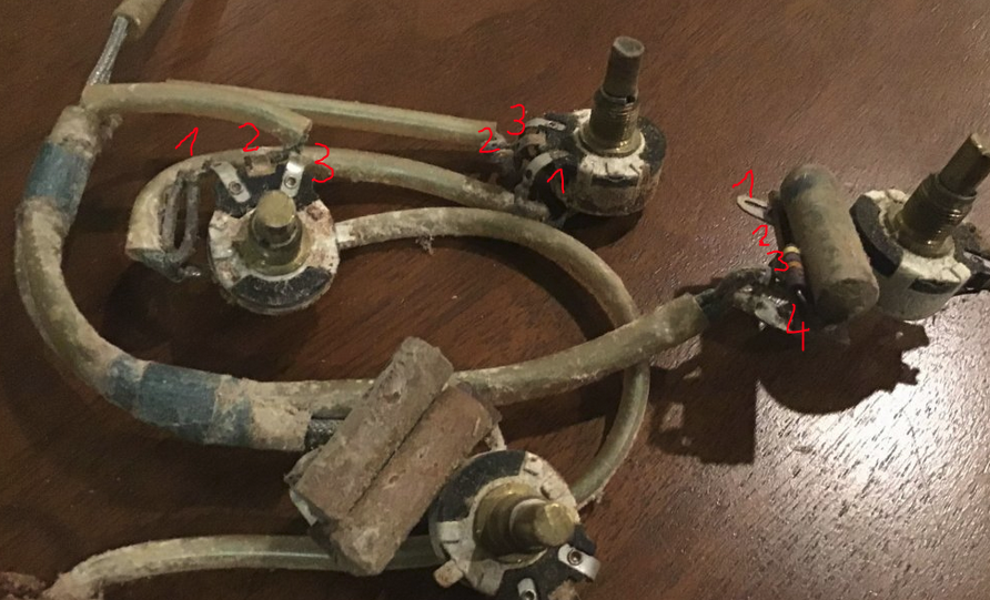
The volume and tone pot location in the guitar also appear backwards related to the pickups. The volume pots are on the top toward the center line of the guitar. The bridge pickup pots are on the left and the neck pickup pots are on the right. I can rotate the harness 90 degrees clockwise and I would have the two volume pots to the left and the neck would be on top like a “normal” four knob configuration. My guess is that was the intent and whoever installed the harness at the factory messed up. I will rotate when I reinstall the harness.

Any insight or thoughts appreciated!
1642877202803.jpeg
1642877228335.jpeg
1642877287868.jpeg
 

BradHK

Senior Member
Joined
Jul 1, 2014
Messages
1,063
Reaction score
2,749
I found a chart on the color code stripes for old caps and the yellow, purple and orange combination on the small cap in the photo above is 0.047. Pretty high for a bridge pickup. I am beginning to think that the output wires from the selector switch were backwards from the factory. If I switched them I would have both volume knobs on the top, the higher cap values on the neck pickup, and the volume pots aligning with the pickups (ie, neck pickup volume pot on the left). I just hate changing something on an original wiring harness in a guitar this old.
 

BradHK

Senior Member
Joined
Jul 1, 2014
Messages
1,063
Reaction score
2,749
Ok, I completely messed up. The cap at the selector switch and the higher value caps at the tone pot are wired to the neck pickup. This makes more sense. The pickup wires go through some original wrap on the way to the selector switch and the pickup wires cross under this wrap. However, that means the selector switch in the up position selects the bridge pickup and the down position is the neck. Strange but that is the only way it will fit into the guitar. At least the volume and tone knobs are in the correct place!
 

SFIV1967

Venerated Member
Joined
Nov 20, 2010
Messages
18,504
Reaction score
9,029
Location
Bavaria / Germany
Guild Total
8
I found a chart on the color code stripes for old caps and the yellow, purple and orange combination on the small cap in the photo above is 0.047.
That's not a cap but a resistor!!! See my answers about the harness and the positioning of the volume and tone pots and the caps in the other thread!

Ralf
 

BradHK

Senior Member
Joined
Jul 1, 2014
Messages
1,063
Reaction score
2,749
That's not a cap but a resistor!!! See my answers about the harness and the positioning of the volume and tone pots and the caps in the other thread!

Ralf
ok, I am obviously slow today. Your wiring harness appears to have one cap per tone pot and the cap on the selector switch has been removed. The difference seems to be mine also has resistors at the tone pots in which the pickup signals go directly through on their way to the volume pots. Why would they have resistors wired in-line and what would be the expected impact on output and tone? I can’t read the pickup ohms past this resistor (for example at the output jack or volume pots) as the reading is much higher (I am assuming due to the in-line resistors). Thanks
 

SFIV1967

Venerated Member
Joined
Nov 20, 2010
Messages
18,504
Reaction score
9,029
Location
Bavaria / Germany
Guild Total
8
I could be wrong as well. It's a bit odd what I see on your wiring, hence I also struggled on quick look.

Have a look at my two tone pots:

1) Neck pickup tone pot:

Orange wire comes from the middle lug of the volume pot (where the pickup is connected to), signal goes through the 30nF round cap and via the green wire to the tone pot. Middle lug of tone pot is grounded, right lug unconnected.

1642894383861.png 1642895464007.png

2) Bridge pickup tone pot:

Same same... Orange wire comes from the middle lug of the volume pot (where the pickup is connected to), signal goes through the 8nF bakelite cap and via the green wire to the tone pot. Middle lug of tone pot is grounded, right lug unconnected.

1642894556223.png


Lug #3 of the volume pots are grounded and lug #1 is connected to the switch. ("decoupled" volume pot).

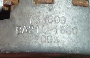
In my case the potentiometers are all 500k, CentraLab (134), 1956, 09th week. BA211-1680 is the part number.

1642894651316.png

The wiring is like this except that the switch and pickup wires on the volume pot are exchanged:

1642895060319.png


Now in your case it is indeed differently connected.

Lets look here at what you called the bridge pup tone pot first:
You say this is the bridge pup tone pot with the 22nF cap. Sounds like a good value.
So instead to lug #1 the signal from the volume pot goes to the middle lug and lug #1 is grounded.
That's more like a modern wiring! I wonder if that wasn't changed at some point in time?

1642895219799.png 1642895487979.png

Now it is interesting what the two "hot" wires do here:

If the capacitor is connected to "4" that would be the signal from the volume pot (you say it is also the signal from the pickup), it goes through the cap into "1" and to the middle lug of the tone pot. All normal.

But that signal would now also go from "4" through a 47k ohms resistor and back to somewhere via "3" !!! (Assuming 3 has no connection to the tone pot.) Now where does 3 go to ??? You say above it goes back to the volume pot then to the output jack?

1642895744400.png

I think we need to clearly find out where the wire on 4 and on 3 come from.

Are you actually sure that is really the bridge pickup tone pot and not the neck pickup tone pot ??? What I believe to see in the harness is that this is the neck pickup tone pot with the one capacitor and the resistor. Again, I could be wrong, just asking.
The wiring harness is made in a way that originally the two volume pots where the upper pots (towards the strings) and the two tone pots the lower pots toward the outside of the body.
So on the left side of the guitar the volume and tone for the neck pickup and on the right side the volume and tone pot for the bridge pickup.

Lets call the two volume pickups Left and Right in the picure.

So to which volume pot lugs goes 3 and 4 from what you called "bridge" tone pot?
And which lug of the volume pots is grounded?

Does the second tone pot with the two capacitors also have such a 47k ohms resistor and the same 1 to 4 lugs? And are those two capacitors connected in parallel? Means having the double capacitance?

1642896821473.png

See also:


Ralf
 
Last edited:

SFIV1967

Venerated Member
Joined
Nov 20, 2010
Messages
18,504
Reaction score
9,029
Location
Bavaria / Germany
Guild Total
8
Lets look at this pickup tone circuit like this: (Bottom view on pots)

1642898189777.png

So how is 1, 2 and 3 connected and where does X and Y go. (X was 4 on the tone pot and Y was 3)

Ralf
 
Last edited:

Default

Super Moderator
Platinum Supporting
Joined
Jul 30, 2007
Messages
13,657
Reaction score
3,086
Location
Philly, or thereabouts
Guild Total
11
That cap on the selector switch sure looks like it is wired to ground to me. The braided shield connects to the ring of the output jack, and to the string ground at the tailpiece?
 

BradHK

Senior Member
Joined
Jul 1, 2014
Messages
1,063
Reaction score
2,749
I will draw out a wiring diagram and post tomorrow (Partly just to make sure I am not going crazy and missing something)

In my harness if you follow the output wires from the pickups, they go straight to the selector switch (with a cap on the neck pickup lug going to ground). From the selector switch the wires go directly to the tone pots. Using the photo below and the corresponding numbers, the wire coming from the selector switch goes to lug 4. There is the large cap between lug 4 and lug 1. Lug 1 then goes to the tone pot and through the pot to ground in the normal way. Lug 2 is just a ground. There is a resistor between lug 4 and lug 3. The wire from lug 3 goes to the volume pot then from the volume pot to the output jack (the output wire from the neck volume pot goes to the output lug on the bridge volume pot then the signal from both volume pots goes to the output jack). This wiring at the tone pot takes the pickup signal through the resistor rather than the resistor being between the pickup signal and ground. Neither side of the resistor is connected to ground. Both tone pots are wired the same way with just different resistor and cap values.

1642913478883.png
 

BradHK

Senior Member
Joined
Jul 1, 2014
Messages
1,063
Reaction score
2,749
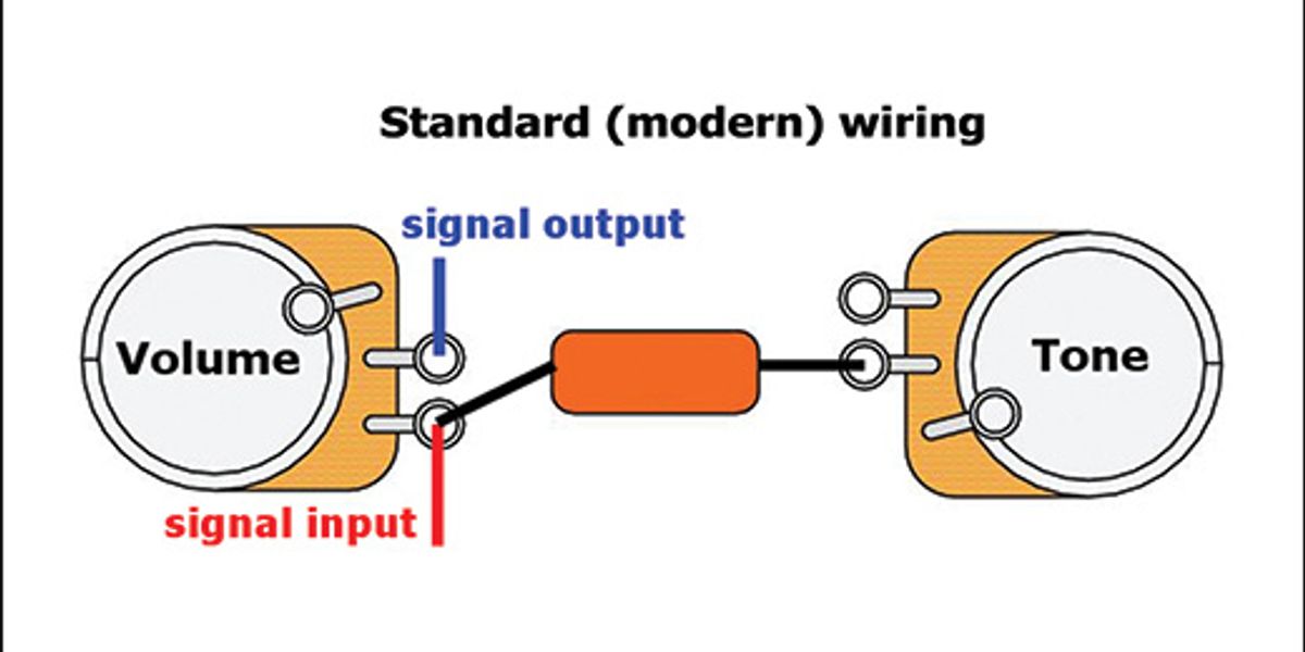
One more quick thought, if lugs 3 and 4 were connected together directly rather than through a resistor the wiring would essentially be “modern” wiring rather than 50’s wiring as the cap and tone pot would be on the input side of the volume pot rather than the output side. I will draw it out tomorrow once I have had some sleep and a coffee...
 

BradHK

Senior Member
Joined
Jul 1, 2014
Messages
1,063
Reaction score
2,749
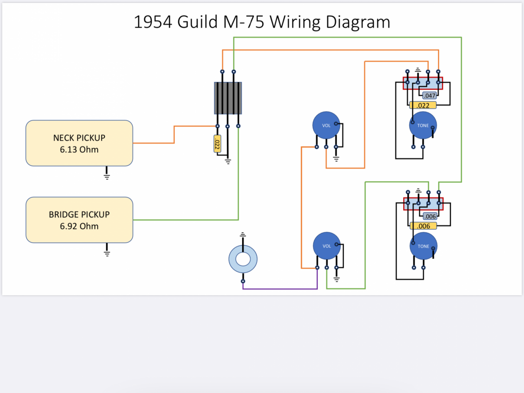
Below is a diagram of the wiring harness:

1642962650118.png
 

SFIV1967

Venerated Member
Joined
Nov 20, 2010
Messages
18,504
Reaction score
9,029
Location
Bavaria / Germany
Guild Total
8
Nice job! What program did you use to draw that?

Let me make a few comments to the tone pots, I added numbers again:

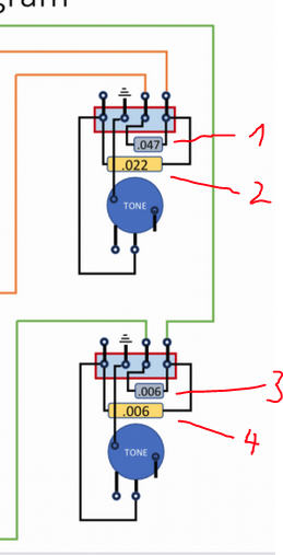
1) that should read not .047 but 47k (as it is a 47k resistor)

2) looks fine

3) Can you take a photograph of that part? If you say .006 wouldn't this be a 6k ohms resistor like the other 47k ohms resistor?

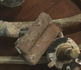
4) You show again a .006 part which should be a capacitor, so that would be a 6nF (0,006 microfarad) cap. But where is the second cap I see in your picture ? It looks like two capacitors to me?


1642965939576.png 1642966142339.png

Ralf
 

BradHK

Senior Member
Joined
Jul 1, 2014
Messages
1,063
Reaction score
2,749
Thanks again for all of your assistance! I just used PowerPoint to create the wiring diagram.

I cleaned up the caps and resistors and below are better photos. You can’t read all of the values on the cap at the neck tone pot but it appears to be exactly the same as the cap at the selector switch so I also included a photo of that cap that shows the values. Thanks again!

neck tone pot: from your numbers above, 1 is the small resistor furthest away from the tone pot and 2 is the large cap closest to the the pot
1642967520795.jpeg
cap at selector switch that appears the same as tone pot cap:
1642967622661.jpeg
Caps/resistors at bridge tone pot (they appear to be identical): from your numbers above 3 is on the top (furthest away from the tone pot) and 4 is on the bottom of the photo
1642967798241.jpeg
 

SFIV1967

Venerated Member
Joined
Nov 20, 2010
Messages
18,504
Reaction score
9,029
Location
Bavaria / Germany
Guild Total
8
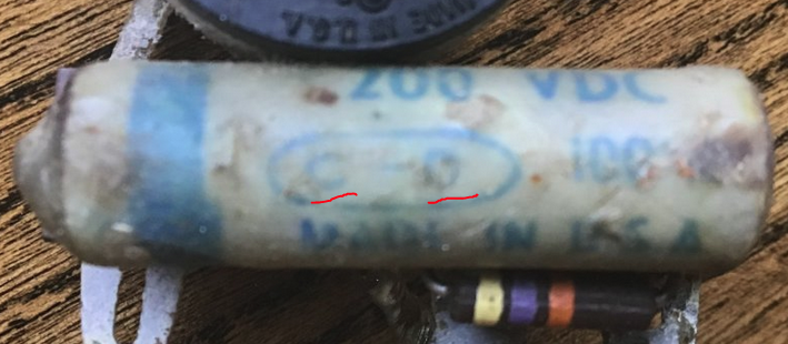
O.k, so the .022 (22nF) caps were made by Cornell Dubilier in South Plainfield, NJ, as can be seen on the C-D logo:

1642969398509.png
Obviously no way telling who made the resistor, which doesn't matter.


And I'd say below those are two type AM molded paper capacitors made by Astron in East Newark, NJ. (Astron logo probably visible)
Both have a value of .006mfd = 6 nF. Connected together in parallel would give that package a combined value of .012mfd = 12 nF. If they are in parallel...
Anyway that means there is no resistor on that bridge tone pot in line with the signal.

But can you please double check once again, aren't the two caps both connected in parallel? Is really only one going to the tone pot and the other would be going back to the volume pot ??? Can you take a picture from the bottom of below picture to show the soldering joints?

1642969677334.png

Ralf
 
Last edited:

BradHK

Senior Member
Joined
Jul 1, 2014
Messages
1,063
Reaction score
2,749
below are some detailed photos. You can see they are both connected to the same lug on one end (far right lug in my wiring diagram where the signal from the selector switch goes). The cap closest to the pot is wired to the lug on the far left which then goes to the tone pot. The other cap/resistor goes to the second to right lug. The pickup signal must go through this cap/resistor. I measured the resistance between the two lugs on the right of the diagram (one comes from the selector switch and the other goes to the volume pot). The resistance at the neck tone pot between these lugs is 39.5 ohms and the bridge is 51.3.

This is the far right lug in my diagram (pickup signal wire coming from selector switch goes to this lug)
1642970968261.jpeg
This is the other end of the circuit board. You can see the cap closest to the pot goes to this lug and then you can see a wire at the same outer lug which goes to the tone pot. The cap/resistor furthest from the pot has a wire that takes it back to the lug that leads to the volume pot.
1642971154464.jpeg

Additional photos where you can see the wire from the end of the cap/resistor looping back to the second to right lug in my diagram:
1642971246584.jpeg
This is a photo from the back of the pot which matches the wiring diagram. From right to left: 1] wire from selector switch 2) wire going to volume pot 3) ground 4) wire going to tone pot.
1642971560333.jpeg
 

SFIV1967

Venerated Member
Joined
Nov 20, 2010
Messages
18,504
Reaction score
9,029
Location
Bavaria / Germany
Guild Total
8
Interesting! Yes that's what I wanted to see.
Anyway, both those 6nF caps are only capacitors, not resistors!

So the tone pot has only a 6nF capacitor, that means the neck pickup should be pretty bright.

Now a 6nF cap in line with the signal means it is like a treble bleed circuit but 6nF is a very big value for that. An odd circuit in my opinion. Maybe others have an idea about the function of that cap. (as well as about the function of the 47k ohms resistor on the neck pickup circuit).

Ralf
 

BradHK

Senior Member
Joined
Jul 1, 2014
Messages
1,063
Reaction score
2,749
Thanks and I am a little baffled with this wiring schematic and why somebody would choose to wire it that way. Having the pickup signals go through either a resistor or a cap seems like your putting a blanket over the pickups. The photos above are of the bridge pickup tone pot.

I was thinking of three options:

1) keep it the way it is, reinstall it once the rest of the guitar is ready and see if I like the tone. I would be taking the risk of having to pull it all back out and reinstall and I still don’t like the pickup signals going through resistors and caps. I feel like I won’t really be able to tell what the pickups actually sound like.
2) remove and save the cap on the selector switch and bridge across the far two right lugs of the circuit boards at both tone caps (wire coming from the selector switch and wire going to the volume pot) to bypass the resistor in the neck circuit and the cap in the bridge circuit. This would keep it close to original and the modifications would be reversible.
3) save this wiring harness as the original harness and just build a new harness with the original pickups. This would eliminate any potential problems and I know it would function as expected but I would not have the original pots and caps in the guitar

I am not decided at this point. Any other thoughts or opinions?
 

SFIV1967

Venerated Member
Joined
Nov 20, 2010
Messages
18,504
Reaction score
9,029
Location
Bavaria / Germany
Guild Total
8
So far just an additional comment about the capacitor on the toggle switch. It seems to definitely help removing it:


Ralf
 

BradHK

Senior Member
Joined
Jul 1, 2014
Messages
1,063
Reaction score
2,749
So far just an additional comment about the capacitor on the toggle switch. It seems to definitely help removing it:


Ralf
Thanks. I have measured the caps and resistor in this harness and the only one that is bad is the one connected to the selector switch. One more reason to disconnect! Using a capacitance meter that cap reads 0.19nF (.00019MFD) and it is supposed to be .022MFD. The same cap on my neck tone switch measures out .037MFD which is a little higher than the .022 spec but still in a good range. The bridge tone cap measures .008 compared to the .006 spec.

I am still unsure what the expected change to the tone is created by running the pickup signal through a resistor on the neck PU and a cap on the bridge PU. I understand the use of caps when they bridge to ground either directly or through a pot and the bleeding of frequencies to ground. However, I am struggling with the frequency impact when they are wired where the only signal going to the pickup is what the cap or resistor allows to flow through. Any thoughts? I have exceeded my limited knowledge of caps at this point. I am still leaning toward bypassing the cap and resistor in which the PU signal passes through on the way to the volume pots.
 

SFIV1967

Venerated Member
Joined
Nov 20, 2010
Messages
18,504
Reaction score
9,029
Location
Bavaria / Germany
Guild Total
8
I am still unsure what the expected change to the tone is created by running the pickup signal through a resistor on the neck PU and a cap on the bridge PU.
The 47kohms resistor in the neck pickup signal path basically only increases the resistance of the volume pot, means it adds 47kohms to the 500kohms of it. No idea what the effect would be, I mean that is simply 10% which a normal tolerance for old pots could already be. So I see no real need for that 47kohms resistor. The capacitors were two times 22nF to ground (one directly on the switch, the second through the tone pot. So that is like a 44nF cap in total. You measure 37nF on the tone pot cap now, so that is fine with cutting out the cap on the switch. No need for it at all.

The 6nF capacitor is something that puzzles me in the signal path of the bridge pickup. The 6nF cap (now 8nF) on the tone pot keeps a lot of high frequencies in the signal path, so the bridge pickups is brighter sounding compared to the neck pickup. I talked to Walter Broes, who has loads of experience with Franz pickups, he said he usually uses 22nF caps.
So having that second 6nF cap now in the signal path also means some high frequencies are blocked on the way to the volume pot. I would have thought you could reach the same result by using a 12nF cap on the tone pot or having both 6nF caps in parallel on the tone pot. Maybe that would be an idea, if both 6nF caps read like 8nF now, that gives you a 16nF cap. Sounds good. And the signal would go straight to the volume pot.

1643569285635.png

Maybe @Default has more ideas.

Ralf
 
Top