Tweed Gibson GA30RV

Default

Super Moderator
Platinum Supporting
Joined
Jul 30, 2007
Messages
13,648
Reaction score
3,075
Location
Philly, or thereabouts
Guild Total
11
As a brief veer on the creamy chocolate goodness of Gibsom amps, my buddy is caring for my GA20 and he can get great crunch out of it with humbuckers and volume at 5. I am going to have to build him one in order to get the Gibson back...
 

capnjuan

Gone But Not Forgotten
Joined
Nov 29, 2006
Messages
12,952
Reaction score
4
Location
FL
Default said:
As a brief veer on the creamy chocolate goodness of Gibsom amps, my buddy is caring for my GA20 and he can get great crunch out of it with humbuckers and volume at 5. I am going to have to build him one in order to get the Gibson back...
Well you are both half-way there and half a world away.

Some time back, the Chief Engineer at Wuzzatronics Sound Labs NZ and I collaborated on a circuit board for the venerable Gibson GA18T; double-barreled glorious 6V6 power w/ Treemalololololo. I think the Chief still has a stuffed GA18 circuit board originally intended for use in his dis-established Guild T1 RVT (he's still waiting for approval from Mark Dronge :wink: ).

They're sweet, smokey amps; no, can't play either Madison Square Garden without a PA or metal with them but it doesn't mean they don't have pleasant tone. These days he's grinding out 4XEL84 Matchless Spitfire clones ... he can solder better than most of us can play :shock: :shock: :shock:
 

capnjuan

Gone But Not Forgotten
Joined
Nov 29, 2006
Messages
12,952
Reaction score
4
Location
FL
Not to mention that you're getting killed by your people in the purchasing department ... :(
 

bluzman

Junior Member
Joined
Jan 25, 2010
Messages
31
Reaction score
0
Location
Very close to Westerly
'57 Gibsonette
Gibsonettef.jpg

Gibsonettet.jpg


'57 GA40
GA40Tele.jpg
 

capnjuan

Gone But Not Forgotten
Joined
Nov 29, 2006
Messages
12,952
Reaction score
4
Location
FL
Hi Bluzman; a mighty fine pair of vintage Gibsons! In another thread, you were talking about the '57 Gibsonette:
bluzman said:
... I saw a picture and didn't haggle and it was fair all around. Mine doesn't have the 12AX7 it has the 6SJ7 and a field coil speaker. It's anemic sounding but it works. It looks like the big cap leaked so I'll replace that and play with tubes. The Kalamazoo Schematics KEA match this one.
Did you ever get it straightened out? It's in remarkable condition. 8)

Those Dr Zs; I can't help but wonder ... are you a Dr Z distributor or do you just know a good thing when you hear one? :D
 

bluzman

Junior Member
Joined
Jan 25, 2010
Messages
31
Reaction score
0
Location
Very close to Westerly
As far as the Gibsonsette goes... It works after new tubes, but it does need the caps replaced.
I think I'm going to do the Gibsonette myself, but the GA40 I'm sending out... probably to Mark at Victoria.
Both amps do work, but not up to par. With so much gear, it's hard to keep up on maintenance as I
like to spend my time playing with it all.

As far as the Dr. Zs go, I'm not a distributor, but I do think they are the best value in a US built hand-wired tube
amp... BAR NONE! So I started adding to my collection along with Marshalls and Fenders and other good sounding
tube amps.

One thing that Mike Zaite (Dr. Z) does right is to keep his amps affordable for the local weekend players like me,
while still building world class amps... Just ask Buddy Whittington, Brad Paisley, Joe Walsh, and me! ;)

Thanks!

PaulT
 

capnjuan

Gone But Not Forgotten
Joined
Nov 29, 2006
Messages
12,952
Reaction score
4
Location
FL
Hi Paul; well ... that's a world-class set of Dr Zs you have 8)

I hope your get your Gibsons running they way you like them!
 

Japes

Junior Member
Joined
Nov 25, 2008
Messages
13
Reaction score
0
Well it's finally done...here are a few pics..I still need to stencil the Gibson into the handle...and if anyone can pm me a photo of the gliders/feet would be appreciated....
Aug2011-0.jpg

Aug2011-3.jpg

Aug2011-6.jpg

Aug2011-7.jpg

Aug2011-8.jpg


I have been studying the schematics to see where the bias resistor is because I popped in some matched mesa boogie 6v6's in there the volume increased but boy did it get hot....dropped back in the originals all ok...thanks to CJ and others who helped...
 

capnjuan

Gone But Not Forgotten
Joined
Nov 29, 2006
Messages
12,952
Reaction score
4
Location
FL
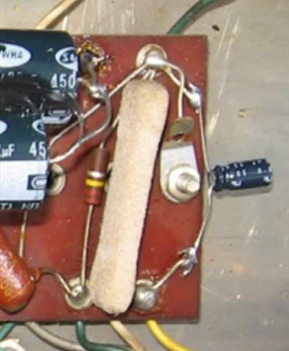
Hi JP: pic below is a GA30RV chassis. The original location of the 6V6 cathode resistor and bypass cap are at the extreme right end of the circuit board viewed from the rear; 250 ohm (not less that 2 watt) resistor and a 25uf/25V bypass cap. The pic is correctly oriented and the upper end of that resistor is grounded back to that terminal as is the (-) end of the bypass cap.

GA30bias.jpg


If you changed the cap; any chance you have the + end grounded? Can you post a pic of your chassis? Love that upholstery work!
 

Japes

Junior Member
Joined
Nov 25, 2008
Messages
13
Reaction score
0
1961GA30.jpg

Nope havent changes the cap havent found the resistor yet still studying the schematic as you can my 61 is point to point ...its a pic from 2yrs ago all electrolytics have been changed...reading an rca manual to help...
 

capnjuan

Gone But Not Forgotten
Joined
Nov 29, 2006
Messages
12,952
Reaction score
4
Location
FL
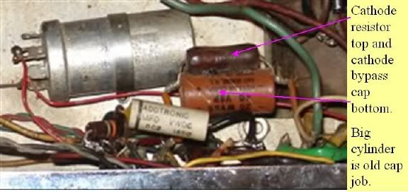
My apologies; I'd forgotten that yours was the earlier model. Pic below IDs the cathode resistor and bypass cap. The most common higher wattage resistors are the sand style; I suggest 5 watts; they're chunky looking but the added dissipation is good ... 250 ohms. That bypass cap needs to go.


GA30bias2.jpg


Hoffman Amps Scroll all the way down to the Sprague 25uf/25W ... it will be perfect. Buy the parts and drain the power supply caps by either using a resistor to bleed the DC to the chassis or just cowboy it; holding an insulated screw driver, touch the tip of the screw driver to one of the hot posts of that can cap and let the shaft touch the lip of the chassis ... you'll get a spark ... hold it there for a little longer ... do the same with the other sections of the cap.

Replace the old resistor and capacitor just like you see it but you must note which end of the old cap is going to ground ... new one the same way.
 

Japes

Junior Member
Joined
Nov 25, 2008
Messages
13
Reaction score
0
Capn thanks for the info...that was an older image to show where/whats here is one from the build you can see the electrolytics are all new.... odd thing is amp was not working until I replaced those last 2 items the resistor & cap you pointed out...
Aug2011-9.jpg
I wouldn't mind converting it to a variable adjustement to really bias the tubes properly...
 

capnjuan

Gone But Not Forgotten
Joined
Nov 29, 2006
Messages
12,952
Reaction score
4
Location
FL
Hi JP: well ... if the tubes are red-plating, usually that's a bias problem. The only other thing I can think of is that you've got the bypass cap connected backwards; + end to ground.

Confirm that there's a jumper between the two 6V6 pin 8s/cathodes; snugly connected?

The schematic for this model shows a choke; does your amp have one? Is it crudded up? Can post pic?

That little white cap with the black band on one end near one of the 6V6 sockets ... Is that one of the .05 coupling caps?

Not sure what you mean by variable. If you mean adding a pot to manipulate plate dissipation, that can only be done in a fixed-bias amp; they go between the source of the bias voltage and the grids.
 

Japes

Junior Member
Joined
Nov 25, 2008
Messages
13
Reaction score
0
Only the new tubes got really hot along with the middle transformer when I replaced the old 6v6 problem went away...I'll take a new proper photo of the innards!!!
 

capnjuan

Gone But Not Forgotten
Joined
Nov 29, 2006
Messages
12,952
Reaction score
4
Location
FL
Japes said:
Only the new tubes got really hot along with the middle transformer when I replaced the old 6v6 problem went away...I'll take a new proper photo of the innards!!!
Okay; the 'middle transformer' is the choke ... it looks like a transformer but it only has two wires; one in and one out. Should look like the thing in the middle:

Trannies.jpg
 

Japes

Junior Member
Joined
Nov 25, 2008
Messages
13
Reaction score
0
DSC07446.jpg
photo of innards...time got away from me! On the up side I bought 10 12ax7 NOS & used which all tested A1....for $2 each....Mullards RcA & GE, EICO mixed....
 

capnjuan

Gone But Not Forgotten
Joined
Nov 29, 2006
Messages
12,952
Reaction score
4
Location
FL
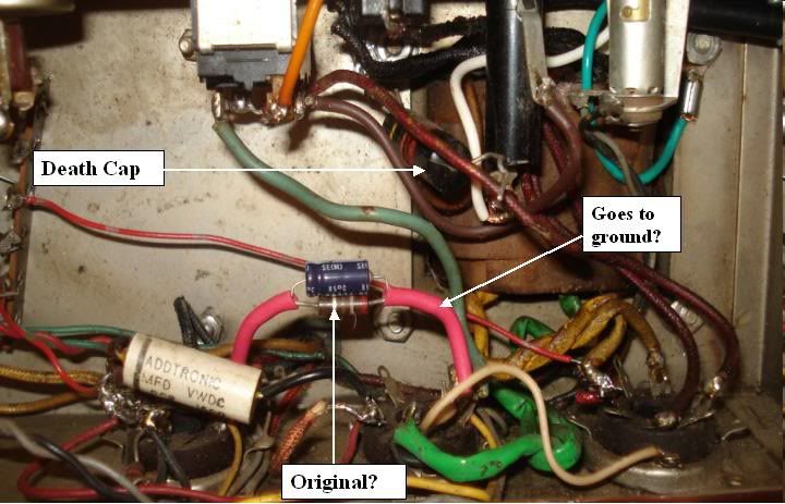
Hi Japes; the 'death cap' can go ... has a down-side if it fails but no upside. Amp unplugged, just snip it out. It wouldn't work with old tubes either if the cathode bypass cap were connected wrong but .. humor me; just confirm that the lead on the visual right goes to ground. According to the schematic, the cathode resistor is supposed to be 250 ohms; red/green/brown. It might be but can't tell by looking at the pic; was/is the second band from the right green? If not, what color was/is it?

japespower.jpg


As far as the Mesa 6V6/s heating up the choke; I suspect one (or both) of them are bad; even if that bias resistor has drifted some (+/- 20%), it shouldn't be enough to upset anything. Past that, I don't have a good guess :?
 

dapmdave

Enlightened Member
Joined
Mar 18, 2009
Messages
7,612
Reaction score
24
Greg Feo said:
Great read, thanks LTG !

The good cap'n was a great contributor to LTG.

All the old amps in heaven are now rocking better than ever.

Dave :D
 
Top