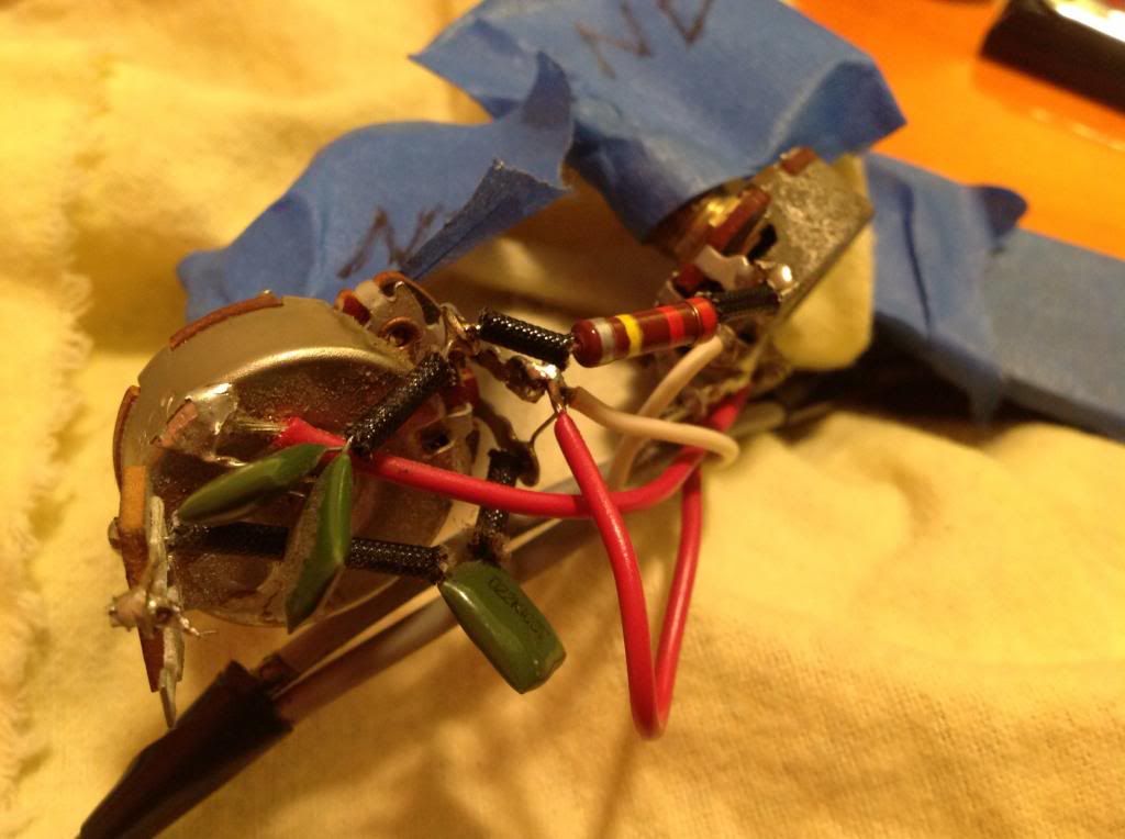
Interesting, two of the 3 capacitors and the one resistor seem to be part of the old suck switch circuit. I would just remove all that stuff.
The capacitors are old "vintage correct" capacitors, I guess I see a 0.022mfd cap (22nF or 22000pF).
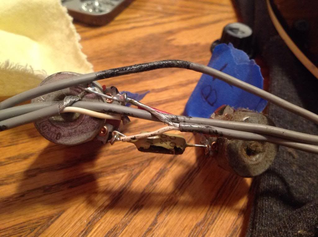
This capacitor below is also original, it is a
10000pF (10nF or 0.01mfd) 200V Mullard 'mustard cap'.
Also you can see all the value of the pots written on the bottom of the pots.
I can give you an example what you might see (but with different pot code and dates):
Pot Code 137 6638 = CTS (Chicago Telephone Supply, manufacturer #137) = 38th week 1966
You also will see a Guild part number like 004019 or 004020 for 500kohms pots, or 004026 for 200kohms or something like this.
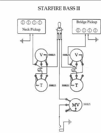
The correct wiring diagram with removed suck switch should look like this:
Mind that it is possible that your bass might have had a 200kohms neck tone pot or even an additional 200kohms bridge tone pot. That is perfectly correct!
(The Starfire IV had a 200kohms neck tone pot but a 500kohms bridge tome pot)
On the Starfire guitars usually the bigger capacitor value like 0.047mfd (or 0.033 or 0.022) is at the neck p/u tone pot and the smaller value, like 0.01mfd is at the bridge p/u tone pot. This should give you a "darker" "jazzy" sound for the neck pickup and a clearer sound for the bridge pickup. Now the lower resistance (200kohms) on the neck tone pot also means that more high frequencies go to ground, so the neck pickup is extra “dark”.
There were several possibilities how the pots and caps are connected, so this is just one version:
Ralf