littlesongs
Member
+100Jeff Haddad said:Wow cap'n, my posts feel so inadequate after reading yours!
I really appreciate the patience and guidance John. It makes a whole lot more sense now.
Cool history! It would be interesting to suss out when the Gibson & Guild designs hit the scene. The Ampeg Echo-Satellite debuted in '61.capnjuan said:Hi Dave; first things first ... have to salute Guild. It made the RC20 Remote reverb/tremolo unit sometime in the early 60s (Hans or Kurt for dates). As Jeff pointed out about the EJ, it too relies on a dry signal from another amp tapping its signal at its speaker:
capnjuan said:The signal heads to pin 11 - the grid of stage 3 ... amplifying stage and phase inverter from where it goes to the 7591s each getting its half of the AC waveform. I'm not completely sure about J2, the auxiliary input ... possibly a mic for yodeling; and I don't understand the function of the shorting arm there but so far, I don't have too.
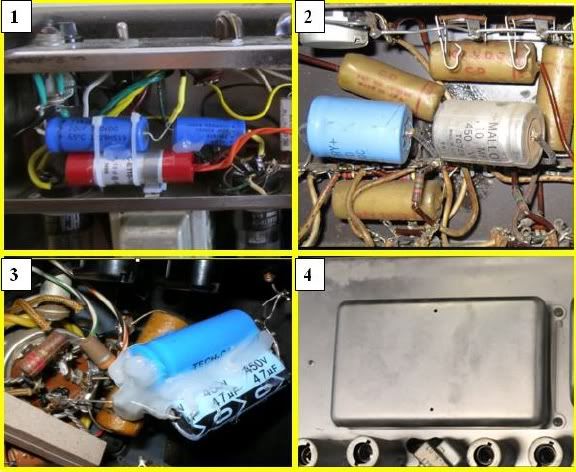
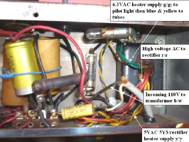
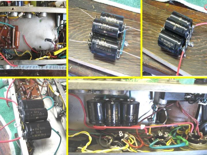
The power in the amp shown below; in the lower right-center, all the taps on the transformer; red for high voltage secondary AC, yellow for 5VAC heaters for the 5Y3 rectifier, and green for the 6.3VAC 7591 and 6D10 heaters. Shown far left the current filter caps and dropping resistors.
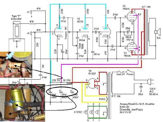
The primary DC (red) goes to the center tap of the output transformer and winds up on the plates / anodes of the 7591s. The magenta is power for the twin screens (pins 4 and 8 ) which are jumpered together. The blue is the power to three sections of the 6D10.
Thanks for showing me the ins and outs of the "plumbing" in there. I will definitely try yodeling when we get it put together. :lol:
capnjuan said:The power supply with all the transformer taps ID'd and the three filter caps on the left (more on filter caps below). Note the 'yellow' cap that doesn't match the others and how its red lead touches the already-scorched power resistor:
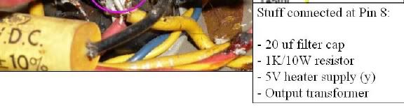
Whoever put that yellow cap in didn't bother to straighten the mess out - see left below. On the right are listed all the pieces and parts that connect to pin 8 of the rectifier and on the left, how tidy and neat the work appears:
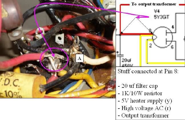
Edit: my screw-up. No high voltage AC on pin 8: should read:
The pin marked A is unused by the tube but Ampeg used it as a convenience tie point for one leg (white) of the incoming 110V service, a black wire leading down and away to the 'death cap' (the lead is sleeved), and the black wire (right center) marked '105' that feeds one side of the transformer. Whoever put the 'yellow' cap in by laying the new (red) capacitor wire on top of the high voltage DC (+/- 325 volts) coming out of the rectifier, left it within a gnat's a__ of the incoming 110VAC :shock: :twisted: :shock: Slosh some water/wine/beer/Stoly in there or get a whopper spike and an arc ... not good.
I might be tracing things out wrong, but if there is proper strain relief, I'd rather go straight from the new cord to the fuse rather than use an extra pin on the tube socket. Would that be wise? The little yellow 600V Cornell-Dublier is the "death cap" and it's gone for good with the new power cord, right?
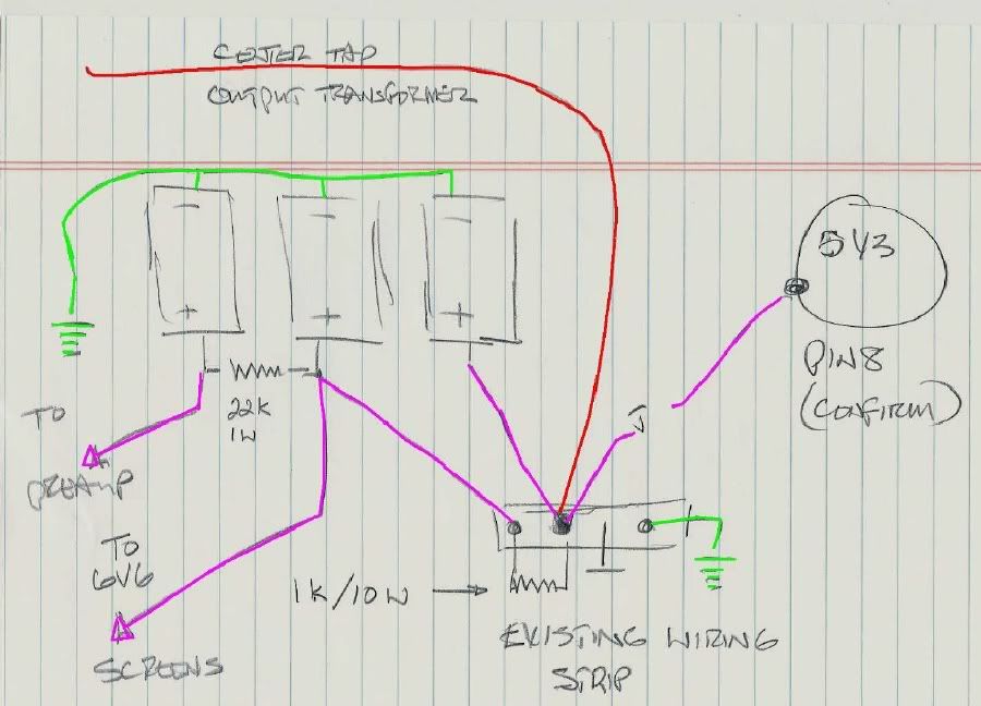
I love that idea!*capnjuan said:I'm proposing something like this; a small rack made of two wiring strips; upper center is the ground side, upper right the hot side. The two dropping resistors; 1K/10W and 22K/1W can be mounted between the lugs on the hot side with leads already in place when the unit is dropped in .. one .. maybe two holes drilled in the chassis:
One way or the other, the condition at the rectifier socket has to get cleaned up.
It is the perfect blend of modular design and point to point construction. Drilling an extra mounting hole or two is no big deal. There will be plenty of room for it once things are cleaned out.
How does this parts list look?
Three 20uf 600V electrolytic capacitors
Two 5pt center ground terminal strips
One 1k 10w wire wound resistor
One 22k 1w carbon resistor
One heavy duty three prong power cord
(*It leaves me wondering why the heck they didn't do it this way in '65. If they weren't gonna go for a three stage can in the Jets, this would have been easier to assemble in quantity and mount in the chassis with a certain amount of haste. On the other hand, I've read the designs were altered to fit the current state of parts supply rather than the concrete plans of the engineers. It could explain the 40uf typo on the schematic too. That error corrected itself since tube rectification was out of the picture when the J-12-D and EJ-12-D came out a few months later. )
Default said:10-12 bucks at the tube retailers!littlesongs said:The tube I may need as a spare someday is a 6D10.

Add: I'm grabbing a copy of "The Guitar Amp Handbook" too.