Fixing my Thunder 1 - how hard?

fearless

Member
Joined
May 19, 2007
Messages
418
Reaction score
0
Location
Melbourne, Australia
I've got a 65 Thunder 1 in "tired" condition - the one with the gold grille cloth. It fires up but just hisses and crackles and has been that way since I bought it years ago and confined it to a corner. I'm now selling my other gear and need to either buy something like a Peavey Classic 30 or fix the Guild.
I am assuming it will need lots of capacitors replaced and new tubes. Maybe a new speaker (although I'd like to keep the original if possible). What sort of budget am I looking at to fix it up (a) parts, (b) time and (c) how hard is it, really?

I'm not a complete electronics novice - I know how to solder properly, have a decent soldering iron and multi-meter, but I don't really know anything about amp schematics and what they mean.
I've seen the excellent advice given to assist others fix up their old Guild amps here, but I'm a bit more of a novice than the folks I've seen getting tips here.
Can anyone be bothered to give "An Idiots Guide to fixing up a 35 year old Guild Thunder One" type coaching?
 

fronobulax

Bassist, GAD and the Hot Mess Mods
Joined
May 3, 2007
Messages
24,769
Reaction score
8,899
Location
Central Virginia, USA
Guild Total
5
Calling CapnJuan. Calling Coastie.

Note that if estimates to the "how much?" question are given, the questioner is not in the USA
 

capnjuan

Gone But Not Forgotten
Joined
Nov 29, 2006
Messages
12,952
Reaction score
4
Location
FL
fearless said:
I've got a 65 Thunder 1 in "tired" condition - the one with the gold grille cloth. It fires up but just hisses and crackles .... capacitors replaced and new tubes. Maybe a new speaker (although I'd like to keep the original if possible).
Hi Fearless;

4-section power supply filter cap; it's usually the primary problem - it's also obsolete and hard to find. There's a company that reproduces them in smallish lots which makes them appear in, and then disappear from, the aftermarket.

In US dollars if you could find one, maybe $40 delivered. The several hot posts at the foot of the can capacitor are populated with 1/2 watt dropping resistors. It's a serious pain to get them off in a condition to be re-used ... vintage doesn't count here ... reliability does ... so they'd have to be replaced ... they're cheap but they're a pain. I'm pretty sure that model has one more loose power supply cap ... another $5 or so delivered and because it sits off by itself, not too bad to replace.

Because we Guilders are smart guys, we also know that although intuition says 'fresh power supply caps' you could have 1 or 2 or 3 other little bitty boo problems that keep it from working that a tech could fix easily but could confound you, I, Beinhard the Brave ... or anybody else trying to help you via post-pics-and-reply. That is, assuming you could get through the cap ordeal, hunting and pecking for other things would amount to substituting everybody else's time, energy, and frustration so that you could save (an Australian) buck or two.

Speaker; the next-best money is for a new speaker;
Fearless' friend: 'how come your amp sounds a little muffled?'
Fearless: 'I kept the old speaker.

Those Guild-badged CTS speakers didn't make it into the Speaker Hall of Fame. If you replace it, you can always offer it to the next buyer in case he prefers a crappy speaker with a worn-out cone. US $75 including delivery ... somebody down there is sure to make a decent speaker.

Tubes: if you get the amp running and a fresh speaker, you can fool around with new tubes. Of course, V1 - the first preamp tube - might be shot but that's considerably less likely than bad caps. My point is that, unless one or more are known bad, the spending sequence usually puts the tubes last. The power tubes are 6GW8s which have been out of production for a long time; not overly expensive and according to Coastie, they show up down under surprisingly often in the ANZAC buy-sell e-market.

You could probably get the ps caps done here for $125-$150 and the virtue of a pro is that he'll find the little nippy-doodle things that also need attention and we would love you all the more for not wearing us out ... :D

I personally would be happy to help within reason ... so long as I get to define what's 'within reason' :wink:

Good luck with your amp!
 

beinhard

Member
Joined
Jul 16, 2010
Messages
260
Reaction score
78
Location
Norway
Guild Total
20
Not much to add, but I want to drive home a point that the captn hinted at: While you will certainly get help here, success will depend on your ability to understand what you are doing while either following or ignoring the sometimes confusing advice you will get.
If you look at previous amp fixing threads you will find at least one where we had the problem pretty much pinpointed, and a suggested solution, but the owner did not have the knowledge and experience to be able to fix it himself.

On the other hand, tube amp circuitry is not rocket science, and learning about how amps work can be a lot of fun.
IMHO the following skills are essential:
- understand the dangers of high voltages
- be able to read a schematic and identify components inside an amp
- know how to solder

Personally I find a multimeter, a scope, a tone generator and some chopsticks indispensable when working on amps.

Sourcing parts for old amps can be a challenge if you want everything to look close to original.
On the other hand there are few components that are so critical to performance that a modern replacement won't work just as well.

I would not do a project like this just to save money, but I would certainly do it for fun, especially if I could get my hands on a Guild Thunderbird amp.

Like John I'm happy to help where I can, when I have time.
As a start, here are some things I will do as a matter of routine when debugging an old amp:
- give all tube sockets, jacks, pots and switches a cleaning and/or workout
- check that voltages through the power supply are reasonable
- check tubes or replace with known good ones
- check or just replace all electrolytic capacitors and any other components that look burned or damaged
- check bias settings if adjustable

beinhard
 

capnjuan

Gone But Not Forgotten
Joined
Nov 29, 2006
Messages
12,952
Reaction score
4
Location
FL
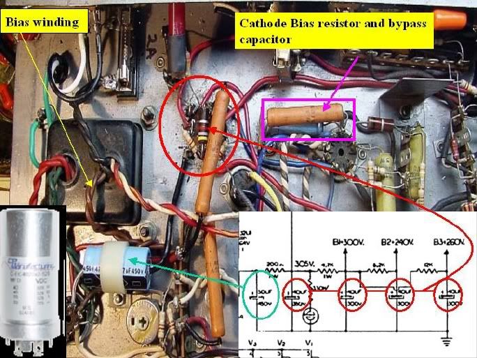
Hi Fearless; the 4-section can cap is circled in red in the upper left center. The clip from the (later) T1 12 schematic (lower right) shows the 4 caps that live in the can and the loose 40uf section circled in green and ID'd in the pic ... it's already been replaced. The can cap in the lower left corner is what come and go in the aftermarket. I don't think I've ever seen the 4X40uf @ 350VDC offered in the aftermarket. As a practical matter, the one in the pic is what I would suggest ... one of it's virtues is that you can actually buy it ... that shouldn't be discounted.

Fearless.jpg


The can cap in the lower left is 2X40uf and 2X20uf; power supply taps B2 and B3 will work very well with less than the specified 40uf in ... besides, you can't buy what's on the schematic anyway so you're already looking for the next-best option.

The job you'd be facing is disconnecting all the wiring to the butt of the cap ... it will have four hot posts and getting rid of the old dropping resistors (which you will have gone out and bought before you start cutting and snipping). The chassis has several slots cut in it to accept the extensions of the can housing; they pass through the slots and get twisted ... Twist-Lock ... to form a tight mechanical bond with the chassis.

It is more likely than not that at least one of these can-to-chassis junctions has been soldered to get an electrical bond. If so, you're going to need a pretty burly solder iron ... better than 100 watts or maybe even a propane torch ... to melt the solder and pull of the old can. Yes, your mind is racing ahead ... if you're going to put back a new can, one or more of the same junctions have to be soldered. No screwing around at this point: get a good ground here or get a good hum.

The best way to go about this is make over-sized hand-drawings of what's there identifying which resistors go between which posts ... this is critical ... mess up and you have too much voltage going someplace and not enough going to another. Accuracy counts.

Finally ... I don't remember whose amp this is but I'm pretty sure it's an odd-ball T1 RVT ... there's a power wire running off to the right that terminates at the reverb amp's can cap but of more technical interest is the 'belts and suspenders' approach to biasing the output tubes. Techno-jabber here; most student amps from this era are either cathode-biased (they have the cathode resistor and cathode resistor bypass cap as highlighted in magenta ... or ... they have a bias winding (yellow arrow/pair of brown wires) ... but it's rare to see both in the same chassis.

Chances are you have or could mooch most of the hand tools you'd need but you need to check to see whether than can cap is soldered to the chassis; if so, as the expresssion goes: 'don't send a boy to do a man's job' (you can hold a 45watt iron there all day long and the heat will just escape into the chassis)

Good luck!

@ beinhard: I understand the Moderators held a secret meeting and you won the 'Iron Man' of the Year Award for your work on the Guild Aspen! :D Best wishes, J
 

fearless

Member
Joined
May 19, 2007
Messages
418
Reaction score
0
Location
Melbourne, Australia
Thank you gentlemen for your sage advice and offers of assistance.
My soldering iron is a 40 watt "boy", so won't be up to this task, I think. I'm leaning towards paying someone else to do it - there is a guy on the other side of town who had a look at the other advice on LTG a few months back and said he'd be up for giving it a go. He is an amp builder so is going to have the right tools and better access to parts suppliers. If I was retired and had the time, I'd love to get to know my way around the schematics better.

The other option I have is to sell it him as-is and let him fix it up for himself. Then I could buy something else with reverb. Which begs the question - what is a 65 Thunder 1 like? I used to have '66 (which also needed work) - is the 65, pretty much the same? I thought they were a generally clean sounding amp - but did see some comments about a Thunder 1 over-driving. Is that the result of how bias is set?
 

john_kidder

Senior Member
Joined
Jun 21, 2005
Messages
3,103
Reaction score
6
Location
Ashcroft, BC, Canada
I have an older T1. It's a bit noisy at low volumes, but sounds great not much louder. Very clean at swing and jazz volumes. And it's really easy to pack around.
 

fearless

Member
Joined
May 19, 2007
Messages
418
Reaction score
0
Location
Melbourne, Australia
Thanks John - I really like the light weight too, and the vintage vibe. So it sounds like not the sort of thing you could play clean at lower guitar volumes and then push into overdrive/compression with the guitar volume knob?
 

fearless

Member
Joined
May 19, 2007
Messages
418
Reaction score
0
Location
Melbourne, Australia
Well, I'm going to get a semi-pro to do it. He's not a full-time amp tech but tinkers with and fixes amps in his spare time. I asked him if could put an effects loop in it and he says he has never done one. So one more question for the experts - how easy would it be?
 

capnjuan

Gone But Not Forgotten
Joined
Nov 29, 2006
Messages
12,952
Reaction score
4
Location
FL
Hi Fearless: in Ampology as in high-jumping, whether somebody can clear 8'-9" depends largely on the skill of the jumper ... or ... flopper ... Dick Fosbury doing his thing:

dick-fosbury.jpg


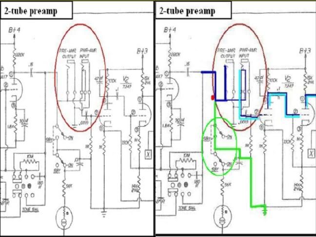
Below are cuts from the Guild single-channel 50watt Thunderbass head ... with an effects loop. The image on the left shows the effects-out and effects-in jacks. Because you are a clever Guilder, you've already noticed that they aren't exactly the same.

On the right (ignore stuff in green), in normal operation, the signal follows the dark blue line moving left to right. The signal appears on the effects-out hot post jack but doesn't go anywhere because there's no cable plugged in. It loops across and up the effects-in hot post, through the contact arm, back down, and on to the next gain stage.

If both jacks were occupied, the signal would leave the amp via the effects-out and come back through the effects-in (signal shown as light blue). If a cable were plugged into the effects-in jack, the plug would physically open the contact arm breaking the normal circuit and the amp-in signal would follow the light blue line. The shorting arm on the effects-in jack prevents both the dry and 'effected' signal from appearing at the same time at the grid of the next gain stage.

thunderloopsf.jpg


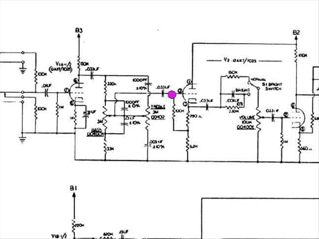
Okay ... so far, you/your man has bought the right jacks and drilled a couple of holes somewhere ... that leaves the question of exactly where in the circuit do you/he cut the jacks in? It's a reasonable question and the only suggestion I have ... and it's just a suggestion ... is the magenta dot on the cut from the (later) T1 12 schematic ... between the .033uf coupling but ahead of that 100K resistor. If they're joined on the amp, I'd separate them.

thunderloopsg.jpg


One more time, there's nothing wrong with the out/in jacks ... the question I have is the location of the jacks in the circuit and whether then effects-in signal will overwhelm the rest of the circuit. Good luck with your amp!
 

fearless

Member
Joined
May 19, 2007
Messages
418
Reaction score
0
Location
Melbourne, Australia
Capnjuan - your knowledge is gold and your blood is worth bottling.
I'll discuss this mod with Mat the amp-man and see what intelligent questions he might come back with.
 

beinhard

Member
Joined
Jul 16, 2010
Messages
260
Reaction score
78
Location
Norway
Guild Total
20
Wouldn't it be better to move the loop to after the cathode follower and the .033 uF coupling cap?
That way you get a lower impedance driving the loop output, and no DC voltage.

With a passive loop like this you have to just use whatever signal level is at that stage of the amp, and that may or may not be ideal for your effects.
An active loop solves signal level and impedance matching problems, but then you need space and heater current for another tube (unless you go solid state).

Another question is how much better an effects loop here will be compared to putting effects in front of the amp.
What kind of effects are you planning to use?

beinhard
 

fearless

Member
Joined
May 19, 2007
Messages
418
Reaction score
0
Location
Melbourne, Australia
Predominantly time based effects like delay, chorus, modulation and probably using a digital multi-FX, something like a POD HD300 or similar. I also quite like the idea of trying out a BBE Sonic maximiser pedal.
However, I might want to use the distortion and pre-amp modelling from time to time in a multi-FX and I assume these would be better placed in front of the pre-amp. Boss GT and some other units are route-able and have FX loops which would allow some of the effects placed in front of the pre-amp and some behind it in the amp's FX loop.
I take your point about impedance matching. It sounds like I would have to check out the specs of the FX unit first.

As engaging as an intellectual exercise as this is, I don't want to lead you on a wild-goose chase. Although time based affects are "supposed" to go in a effects loop, I have used them in front of an amp before and I thought they sounded OK. I'm starting to think an FX loop mod may not be worth it. My guitar skills are modest enough that I should probably be investing money in guitar lessons and time in practice, rather than chasing incremental tonal improvements!
 

beinhard

Member
Joined
Jul 16, 2010
Messages
260
Reaction score
78
Location
Norway
Guild Total
20
Assuming that what you want is to have effects applied after distortion, there are different options depending on how you get distortion (disregarding signal level and impedance matching issues here).
If you use a distortion pedal, effects between pedal and amp should work fine, but if you are overdriving the preamp section of your amp an effects loop is better.
If you crank your amp to power stage distortion levels neither of these will do what you want.

A solution that can work for all these cases is to tap signal from the speaker output and feed that through effects and into a separate amp and speaker.
The Thunder 1 Reverb does this, but only with reverb of course.

I have never seen or heard a T1 in real life, but looking at the schematic I would not expect much preamp distortion from it.
Maybe an effects loop is not the best solution here.

I'm not much of a player myself, but fooling around with equipment trying to find "the sound" is still fun.
Talking about intellectual exercises, I'm trying to redesign an amp I built from a kit a few years ago. It has a very small chassis, only room for 4 tubes and 3 pots.
Trying to figure out how to get the tone and features I want into that has me going around in circles!

beinhard
 

capnjuan

Gone But Not Forgotten
Joined
Nov 29, 2006
Messages
12,952
Reaction score
4
Location
FL
Hi Fearless and thanks for the nice words. Other than to say that since my suggested location ... which I'm not big on anyway ... would have been downstream of that .033uf cap, there wouldn't have been any DC present, I yield completely to beinhard on the subject; knowing what to do and where to do it are two different things.

Past that, I admit to being a low-tolerance person when it comes to 'try-this, try-that' ... especially when it comes to trying to make any amp into something that it isn't. What you have there is a mid-'60s practice amp with a somewhat dry tone that puts out maybe 12 watts downhill.

I think it's great that you want to have your Guild amp running well ... what can be better than Guilders celebrating Guild Goodness? If you get the amp running well, spring for a new speaker, and it still isn't the amp you want ...well ...

Good luck with it whatever you decide to do!
 

beinhard

Member
Joined
Jul 16, 2010
Messages
260
Reaction score
78
Location
Norway
Guild Total
20
capnjuan said:
Past that, I admit to being a low-tolerance person when it comes to 'try-this, try-that' ... especially when it comes to trying to make any amp into something that it isn't.
I wish I said that.
I wish I would listen when somebody says that.
Then maybe I could move on to actually playing music instead of endlessly looking for solutions to problems I have invented.
:lol:

beinhard
 
Top