Hi to All.
This forum has helped me on several occasions with Guild guitars and their repair. I'm hoping I might tap a couple of the amp gurus on a ac cord replacement.
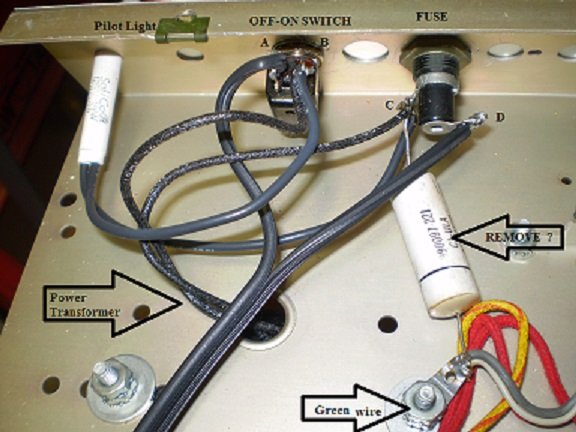
This amp is not a Guild unit. It is an early 1970s Montgomery Wards solid state amp that belongs to a friend of mine. It's been sitting in his closet for years and now that we have his Guild Starfire up and running again he wanted to use his amp with it. In checking it over for him the amp works flawlessly and sounds really nice! The only issue I was concerned about was that it has a two prong cord. In checking the amp by running one lead of my digital VOM into the ground plug of the outlet where the guitar ac cord in plugged into and touching the guitar strings with the other lead I found 120V ac with the cord plugged in one way and if I reserved the AC plug almost none. Not a good situation!!! I want to replace the cord with a 3 prong unit . I have soldering experience and feel I can do this for him as a friend. I do have a couple of questions (Please refer to the attached picture.)
1# remove the "Death Cap" as marked Correct?
2# Attached the green lead to point marked on the picture
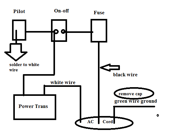
#3 My major questions deals with the white and black wired on the new cord. (For reference I have labeled the components and assigned Letters to the solder joints
#4 Will I need to rewire any wires that are currently attached to the on -off switch ? (marked A & B) (its a simple on-off switch) There is no ground reverse switch on the amp, the fuse holder (marked C & D) ,or 120 Volt power lite, or the AC power transformer leads (Attached to B & C.
#5 If no rewiring for step #4 is needed at which points do I solder the White lead and Black Lead?
Any help would be appreciated and thanks in advance!
dadroadie
This forum has helped me on several occasions with Guild guitars and their repair. I'm hoping I might tap a couple of the amp gurus on a ac cord replacement.
This amp is not a Guild unit. It is an early 1970s Montgomery Wards solid state amp that belongs to a friend of mine. It's been sitting in his closet for years and now that we have his Guild Starfire up and running again he wanted to use his amp with it. In checking it over for him the amp works flawlessly and sounds really nice! The only issue I was concerned about was that it has a two prong cord. In checking the amp by running one lead of my digital VOM into the ground plug of the outlet where the guitar ac cord in plugged into and touching the guitar strings with the other lead I found 120V ac with the cord plugged in one way and if I reserved the AC plug almost none. Not a good situation!!! I want to replace the cord with a 3 prong unit . I have soldering experience and feel I can do this for him as a friend. I do have a couple of questions (Please refer to the attached picture.)
1# remove the "Death Cap" as marked Correct?
2# Attached the green lead to point marked on the picture
#3 My major questions deals with the white and black wired on the new cord. (For reference I have labeled the components and assigned Letters to the solder joints
#4 Will I need to rewire any wires that are currently attached to the on -off switch ? (marked A & B) (its a simple on-off switch) There is no ground reverse switch on the amp, the fuse holder (marked C & D) ,or 120 Volt power lite, or the AC power transformer leads (Attached to B & C.
#5 If no rewiring for step #4 is needed at which points do I solder the White lead and Black Lead?
Any help would be appreciated and thanks in advance!
dadroadie