I was wondering if anyone knows about replacing the power caps in a 1966 Thunderbass amp. I've done some searching, and the one schematic I found is really hard to read. The amp works, but the old parts are a little scary. There is one cap, wrapped in paper, that really worries me. It has a 250mFd 275VDC rating. I don't know if this is a single or multiple can. Any info would be great.
You are using an out of date browser. It may not display this or other websites correctly.
You should upgrade or use an alternative browser.
You should upgrade or use an alternative browser.
Thunder Bass amp - recap?
- Thread starter coffeetom
- Start date
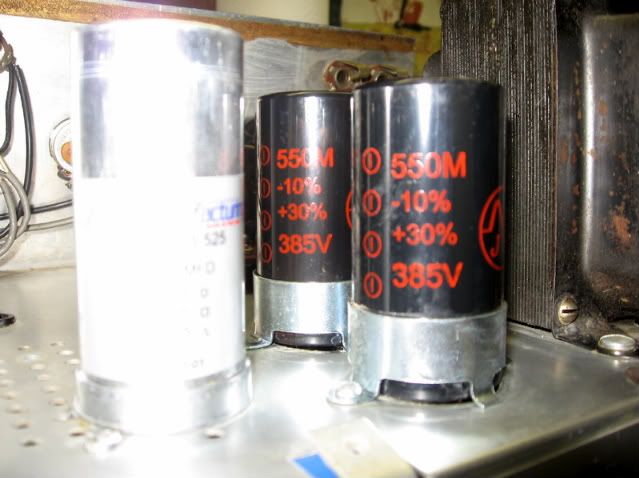
Hi Coffeetom and welcome to the LTG BB: I have several schematics but need to know how many tubes you have in the preamp; this model was sold in 2/3/4-tube configurations. You can PM or email me with your email address, I'll send you the schematic. IIRC, the 250uf/275V cap is in series w/ another of similar value/rating; the primary B+ is taken from the junction. Depending on model, there could be as many as four can caps; two large uf/high voltage, one 3 or 4-section can cap for the screens, driver, and pre-amp (and other preamp if a two-channel model), and one 2-section can cap for the bias. If you're uncertain, post a pic of the tube deck; alternatively, if you can't figure out how to post a pic, then you can attach a file to your post.
Regards, CJ
Regards, CJ
Your welcome Tom; willing to help or cheerlead ... whichever. Are you going to try it yourself or take it in? FWIW, if your workbench isn't already stocked with some tools, there's maybe another $150-odd in stuff like 100w-140w solder 'gun' to break the solder joints on the twist locks, a switchable 25w/45w soldering iron, straight/curved hemostats for handling small stuff, DVM, solder-sucker of some kind and excluding a Variac (more on this below) ...
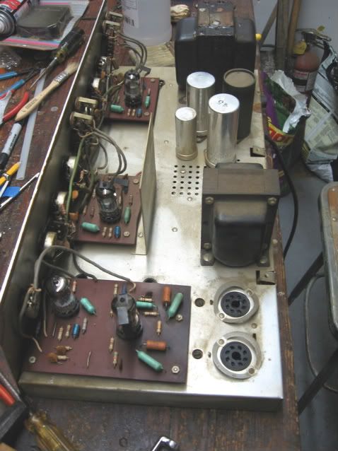
What the tube deck of Tom's amp looks like; like mine used to:
Except for the bias caps, finished work:
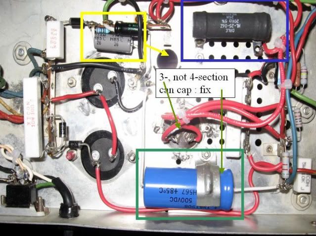
Workarounds: The yellow box and arrow indicate where the two loose bias filter caps are and the arrow indicates where the old 2-section can cap used to be; no longer in production hence the workaround. The green box indicates the new loose 4th 40uf/500V cap. Unless WeberVST is now making one, there is no commerically available 4-section 40uf/450V-500V can cap. Finally, in the blue box is the replacement power resistor unique to the 8417 to 6L6 conversion. When the amp is on the bench next, it will be moved to the tube deck in vertical mount to promote better heat dissipation.
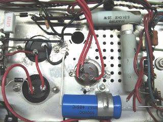
25 watt power resistors: if your amp has these two light blue barrel-style resistors, they need to be hot-checked for drift and visually checked to see that they haven't started to melt the insulation on the adjacent wiring. As you can see, the one on the right has started to diassemble itself; the resistive element is sliding out of its ceramic casing. It also had flecks of red insulation melted onto the housing because the resistor leads weren't strong enough to support the suspended weight of the resistor from pressing against the B+ wiring passing over it when the amp is correctly oriented. The resistor up top has black smears of melted insulation on the upper edge of the right end because the amp, when originally finished, didn't allow enough separation / air between the resistor and the rest of the wiring;
Notes:
Power resistors: I started with the intention of re-building the entire supply; not just converting to 6L6 operation. If I'm going to be messing with it, IMO there's no point in leaving in a $1.00 resistor somewhere that might fail down the road. When I bought my parts, I didn't care about hot-checking resistors because I was going to replace all them anyway.
Variac: There is maybe a 1 in 50 chance that, after replacing capacitors and upon power up, one or more of them can blow their silly heads off. In an amp like this one with a solid state rectifier, the caps see an instantaneous load of B+ as soon as the amp is switched on. If one (or more) of the new caps has a factory defect or is otherwise unhappy, they can fail from the start. The 'fix' is a Variac; a variable transformer with wall voltage input and output varying from 0 to 120VAC. The process is to slowly increase the voltage from 0 to 120VAC over several hours time. This allows the caps time to cook or burn in moderating the risk of instantaneous failure. Variacs cost between $50-$150.
B+: I don't know what your experience or background is but there is B+/DC energy stored in your existing caps. If you're going to tackle this, you must bleed the energy out of the charged caps by connecting each positive terminal to chassis ground using a 5-10watt/100 ohm resistor (resistance can vary +/-; only wattage is important), hold/wait a bit, check for presence of DC with meter, if 0, go to next section, if not, repeat and continue until all the charge is bled out. Alternatively and depending on how well you can resist flinching, you can always short the caps to ground with a screw driver cowboy style ... still need to check that no DC is present.
Welcome again Tom and good luck with your project! CJ
What the tube deck of Tom's amp looks like; like mine used to:
Except for the bias caps, finished work:
Workarounds: The yellow box and arrow indicate where the two loose bias filter caps are and the arrow indicates where the old 2-section can cap used to be; no longer in production hence the workaround. The green box indicates the new loose 4th 40uf/500V cap. Unless WeberVST is now making one, there is no commerically available 4-section 40uf/450V-500V can cap. Finally, in the blue box is the replacement power resistor unique to the 8417 to 6L6 conversion. When the amp is on the bench next, it will be moved to the tube deck in vertical mount to promote better heat dissipation.
25 watt power resistors: if your amp has these two light blue barrel-style resistors, they need to be hot-checked for drift and visually checked to see that they haven't started to melt the insulation on the adjacent wiring. As you can see, the one on the right has started to diassemble itself; the resistive element is sliding out of its ceramic casing. It also had flecks of red insulation melted onto the housing because the resistor leads weren't strong enough to support the suspended weight of the resistor from pressing against the B+ wiring passing over it when the amp is correctly oriented. The resistor up top has black smears of melted insulation on the upper edge of the right end because the amp, when originally finished, didn't allow enough separation / air between the resistor and the rest of the wiring;
Notes:
Power resistors: I started with the intention of re-building the entire supply; not just converting to 6L6 operation. If I'm going to be messing with it, IMO there's no point in leaving in a $1.00 resistor somewhere that might fail down the road. When I bought my parts, I didn't care about hot-checking resistors because I was going to replace all them anyway.
Variac: There is maybe a 1 in 50 chance that, after replacing capacitors and upon power up, one or more of them can blow their silly heads off. In an amp like this one with a solid state rectifier, the caps see an instantaneous load of B+ as soon as the amp is switched on. If one (or more) of the new caps has a factory defect or is otherwise unhappy, they can fail from the start. The 'fix' is a Variac; a variable transformer with wall voltage input and output varying from 0 to 120VAC. The process is to slowly increase the voltage from 0 to 120VAC over several hours time. This allows the caps time to cook or burn in moderating the risk of instantaneous failure. Variacs cost between $50-$150.
B+: I don't know what your experience or background is but there is B+/DC energy stored in your existing caps. If you're going to tackle this, you must bleed the energy out of the charged caps by connecting each positive terminal to chassis ground using a 5-10watt/100 ohm resistor (resistance can vary +/-; only wattage is important), hold/wait a bit, check for presence of DC with meter, if 0, go to next section, if not, repeat and continue until all the charge is bled out. Alternatively and depending on how well you can resist flinching, you can always short the caps to ground with a screw driver cowboy style ... still need to check that no DC is present.
Welcome again Tom and good luck with your project! CJ