Cool schematic diagram, GAD.
Let's walk through it.
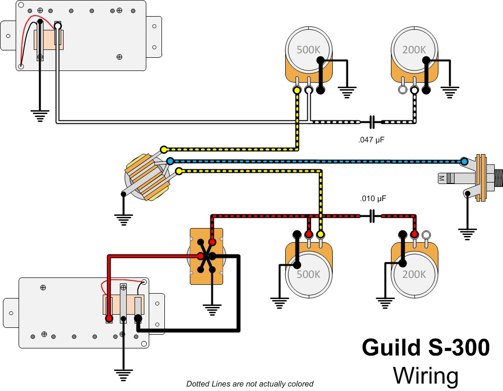
Looking at the neck pickup section alone, the signal comes from the pickup, and goes to the volume and tone pots in parallel, but there is a .047 micro farad capacitor in between them. I assume that is to filter what frequencies get to the second potentiometer. Is this what makes it a tone control rather than just contributing to the volume ? I need some help on how that pairing works, I guess. The signal comes from the volume pot to the selector switch and out to the jack.
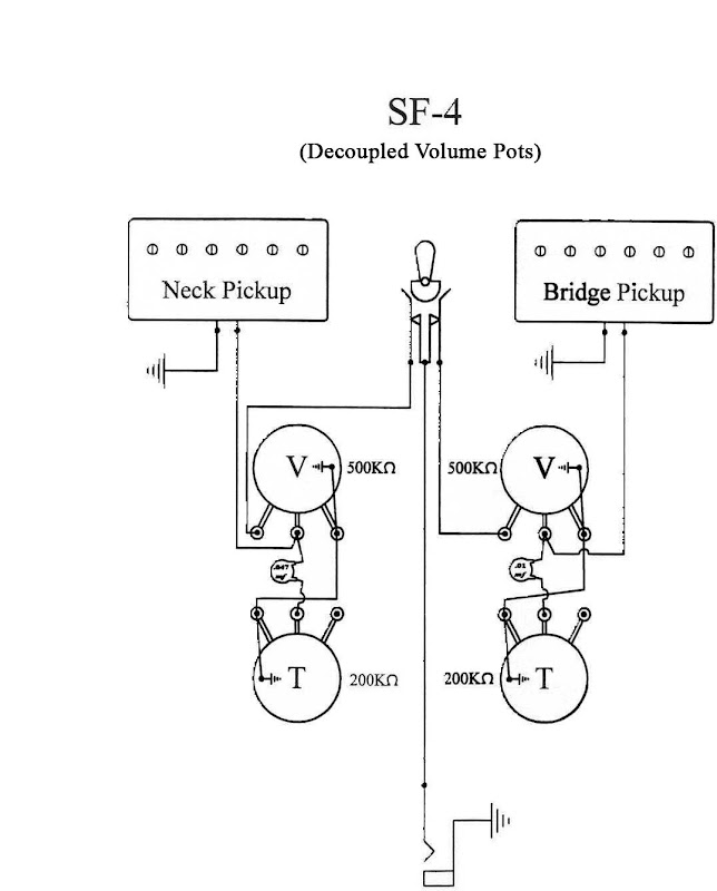
The bridge pickup system could be exactly the same, but with a smaller cap in the knob combination. But, what is the switch in this section ? Obviously , it's part of the guitar you are reviewing, and not a standard two pickup system, like my Starfire.
When the two pickup systems are both in play, in the switches middle spot, I could see they would each be seen as in parallel with each other ( Bridge and neck pickups in mean ). With that in mind, would the effects of the tone pots and volume pots do things to the overall sound because the signal goes through both before it hits the jack. Just like resisters in parallel ?
")