Looking at an Ampeg Gemini 1

Mark51

Junior Member
Joined
Nov 19, 2006
Messages
28
Reaction score
0
Saw this in a local shop. A bit dusty and dirty but looks mostly original. Newer handle and maybe power cord. Jensen dates to 1966, so does the reverb pan. Sales guy said "all original and no issues". It was quiet (no loud hum) but I didn't have time to plug in a guitar. Only a couple small pieces of covering missing on a corner (smaller then a quarter). Has the pedel, cover, and casters. Also has envelope inside with original warrantee card and troubleshooting sheet. They have had it since last summer with starting price at $650, now at $600. I said "everybody wants a Reverberocket, Gemini 1's go cheaper." He said he'd take $450. If he had said $350 I would have walked out with it. I'm going back tomorrow and play it a bit. I'll see what he does with cash on the counter.

Question is, what are these going for today in the north east part of the country?

Thanks.

Mark
 

mad dog

Gone But Not Forgotten
Joined
Feb 1, 2007
Messages
1,269
Reaction score
240
Location
Montclair, NJ
Mark:

Depends on the shape they're in. Prices range these days anywhere from 400 to 800 in the northeast, generally. Vintage shops go for higher, so they sit for long periods of time. 450 is a good price for this one is my guess. You could hold out and wait for one in perfect condition, but they'd certainly be asking more.

MD
 

capnjuan

Gone But Not Forgotten
Joined
Nov 29, 2006
Messages
12,952
Reaction score
4
Location
FL
mad dog said:
... 450 is a good price for this one is my guess. You could hold out and wait for one in perfect condition, but they'd certainly be asking more.
Hi Mark; I agree w/ mad dog ... $450 or so is pretty good ... a better-looking model would just cost that much more. Schematic here. A bit of a mosh-pit of tubes in there ... 6CG7 two-stage reverb driver, a not-inexpensive 7199 phase inverter/driver, and a pair of 7591s out; cathode bias, solid state rectifier ... ought to be good for 25 watts or so. The Gemini 1 uses an opti-coupler to connect the tremolo to circuit. Out of stock at Fliptops. If the trem in the amp you're looking at isn't working, this is normally the reason why. Good luck! CJ
 

Mark51

Junior Member
Joined
Nov 19, 2006
Messages
28
Reaction score
0
Everything works!

A few more tears in the blue covering on the bottom and back then I saw last Thursday but I got it for 375 plus tax.

The fun begins tomorrow. I'll get it on the bench and check things over. Wash some of the dirt out of the covering and polish up the chrome.

Have you guys used the cap cans Fliptop offers?

Any unusual things to look out for with these?

What bias point do the 7591's like?

Thanks.

Mark
 

capnjuan

Gone But Not Forgotten
Joined
Nov 29, 2006
Messages
12,952
Reaction score
4
Location
FL
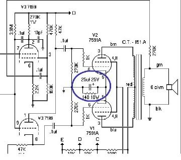
Hi Mark and congratulations! I can't think of any reason not to use the multi-section caps from Fliptop; as good a source as you'll find. I don't know the precise bias point of 7591s. In you amp, it may not matter anyway. If it's built like the schematic linked above, the bias is set by the 140 ohm / 10 Watt cathode resistor and 25uf / 25V bypass cap.

There are several versions of the Gemini 1 (Gemini 12) schematic floating around and I couldn't say for sure whether there's a model with fixed bias or not but if it's built like the linked schematic, there is no separate bias supply to adjust or piddle with - the bias is set by the cathode resistor. Pics if you get a chance. CJ

Edit
: as shown below:

geminibias.jpg
 

Mark51

Junior Member
Joined
Nov 19, 2006
Messages
28
Reaction score
0
Well, mostly good news. Only one resistor swapped out. The 120K from pin 6 on the 6CG7. They put 2, 60K 1/4 watt resistors in series. I'll fix that with 1 watt carbon film resistors. All the electrolitic caps are original. I have 20/450's and 25/50's on hand but will have to order the 80/40/30/20 cap can from fliptops. May just order their cap kit for the G12 which has a 33X2 cap to replace the 20's. A cleaner fit.

Now the bad news. The output transformer has been replaced. It has a Fisher Radio Corp. multi tap OT, p/n T991-116-2A, and they are using the brown lead. From what I could find on the net, it's a 6.6k-4/8/16 OT that Fisher used in alot of 7591A powered receivers. The brown lead should be the 4ohm tap. They used the 16 ohm tap for the negitive feedback. Havn't decided if I'll order a replacement from Fliptops or not. Does anyone have the specs for Fliptops OT?

Mark
 

bunuel

Junior Member
Joined
Oct 25, 2009
Messages
69
Reaction score
0
Might want to consider a Magnetics Components Classic Transformer from Triode Electronics. Great sound, very affordable. Put one in my ol' 60s Ampeg Jet after the orig. output xformer went down. I'd had it for a loooong time before the orig. shorted out and the MCC had it sounding better than with the orig. The crackerjack tech. had rec'd a Merc. Mag. or Heyboer, but I figured I'd give the MCC a try because it was so little, I wouldn't be out much. Glad I did. Also my tech (who loves vintage ampegs) was floored by how good the MCC sounds. More discussion about these x-formers at http://www.thegearpage.net/board/showth ... 223&page=2

BTW, hope yr enjoying that Gemini I, I've been playing thru '60s ampegs for 20 yrs & love 'em, but the Gemini is one of the absolute best amps ever!
 

Mark51

Junior Member
Joined
Nov 19, 2006
Messages
28
Reaction score
0
Just looked at MC's website. I don't see an OT listed for a Gemini 1.

Mark
 

bunuel

Junior Member
Joined
Oct 25, 2009
Messages
69
Reaction score
0
After checking out the MC offerings, the tech picked out the replacement x-former & told me that anything that was up to spec. for 2x 6v6 (e.g. fender deluxe & many others) should fit. Went thru triode elec., just because I've found their service to be exceptional. Case in pt., the tech told me they sent out the wiring diagram to him w/in about 2 working hrs after his request.

I'm not & won't pretend to be a tech (even on the internet), but that's how it went down & much to my satisfaction.

Another option is the OTs avail. from Weber. Great Co, great customer service & very helpful. Their OTs are quite affordable & I've had a coupla friends use then as replacements when their orig. OTs died (vintage Airline & vintage Fender), both were really happy w/'em. Almost went that direction (god bless & RIP ted weber), but decided to try MC because of the made-in-Chicago thing, which means something if one's into vintage amps (e.g. Valco, etc.)

Always a drag when an OT goes down, but it's great that there's some very affordable very great sounding options available thru folks known for great customer service!

Hope you find what you need, the ol' geminis are monsters when they're running right.
 

Mark51

Junior Member
Joined
Nov 19, 2006
Messages
28
Reaction score
0
Update.

New electrolytics with a Fliptops cap kit installed. All scrubbed clean and ready to go .... but. The loud hum is still there so I pulled the preamp tubes one at a time and found the hum stopped when I pulled V5, the 12AX7 for channel 1. Tried several new tubes but hum is still there. So it's back to the bench to check the resistors and caps for V5. Voltages looked good compaired to the schematic on the back panel so it may be one of the caps. They are a mix of CD's, some yellow and some green. Big question is how do you check the components in the molded cracker attached to that small board with the pots. Any thing else to look out for?

Mark
 

capnjuan

Gone But Not Forgotten
Joined
Nov 29, 2006
Messages
12,952
Reaction score
4
Location
FL
Mark51 said:
... The loud hum is still there ... stopped when I pulled V5 ... , the 12AX7 for channel 1 ... question is how do you check the components in the molded cracker attached to that small board with the pots.
Here are two schematics; is either one a close match for what you have?
Gemini 12 V1
Gemini 12 V2
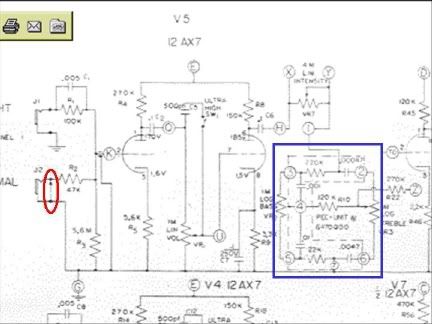
This fragment is taken from V2 showing channel 1 (same as channel 2) highlighting:
1. In blue: what I think it is you're talking about ... a PEC ... packaged electrical component ... a 'factory' part. I don't know how to test them but, unlike a photo-coupler, they rarely go bad.

2. In red: the shorting bar on the 'Normal' input jack ... same as channel 2.

ampegGem1PEC.jpg


If you pulled V5 and still have noise, then the noise is between the input jacks and the grid of V5A ... and not downstream including the PEC. You might think about cleaning the input jacks and the volume pots too. If that doesn't help, turn it on and push on the shorting bar/s with a chopstick to see if you can get the noise to vary. The contact between the hot post and the shorting arm can get dirty. And, over time, the shorting bar can lose it's tension compromising the contact with the hot post.
 

Default

Super Moderator
Platinum Supporting
Joined
Jul 30, 2007
Messages
13,671
Reaction score
3,101
Location
Philly, or thereabouts
Guild Total
11
If you disconnect the signal wire to the grid (pin 2) and you still get hum, you have a better guess at where it would be. It's cheap enough to throw a new jack in and you can also check the dressing on the signal wire, just in case it's something simple. The hum will go away since you're pulling two gain stages, but you should suspect the mechanical connections too.
 

capnjuan

Gone But Not Forgotten
Joined
Nov 29, 2006
Messages
12,952
Reaction score
4
Location
FL
Mark51 said:
When I pulled V5 the hum stopped.
Hi Mark; then it's either between the input jack and pin 2 or a problem with V5's plate or cathode resistors or possibly C2, that .1uf inter-stage coupling cap, is leaking DC. You've subbed in a known-good 12AX7?
 

Mark51

Junior Member
Joined
Nov 19, 2006
Messages
28
Reaction score
0
Yes, I tried a couple new 12AX7's. I replaced the .1 and .022 coupling caps with M150's. Did not swap the .1 going to ground. Still hums. Low hum with vol at 0, gets louder as the pot goes to 10. Ch 2 does the same but with much less hum as would be expected from a lower gain stage. One thing, Ch 1 input goes to pin 7 on V5. They swapped the 2 halves of the tube around but I don't see where that should matter. And they have the heater wires swapped for this tube only.

All voltages off filter caps match within a volt or two. V1 & V2 run 360-363, 14.4 on pin 5, all heaters at 3.0.

Numbers in brackets are from schematic for readings that are more then a little off. Also, schematic looks to have numbers reversed for the pins on V4.

V3 pins are 1/233, 2/66(125), 3/47, 6/2.0, 7/.001, 8/45, 9/28(15)
V4 pins are 1/179, 2/0, 3/1.7, 6/161, 7/0, 8/1.6.
V5 pins are 1/182, 2/0, 3/1.7, 6/160, 7/0, 8/1.6
V6 pins are 1/96, 2/0, 3/3.4, 6/217, 7/0, 8/4
V7 pins are V1/93, 2/0, 3/0.6, 6/186, 7/0, 8/4.8

So, a couple voltages are off. V3 pin 2 is low and pin 9 is high.
V4 and V5 are close. V6 looks like the 2 sides are swapped around but readings are close. V7 looks OK.

Ideas??

Mark
 

capnjuan

Gone But Not Forgotten
Joined
Nov 29, 2006
Messages
12,952
Reaction score
4
Location
FL
Mark51 said:
Yes, I tried a couple new 12AX7's ... I replaced the .1 and .022 coupling caps with M150's. ok

Did not swap the .1 going to ground. The .1uf to ground (C7) is the cathode resistor bypass cap ... If you have another .1uf around, I'd replace that bypass cap. Not just because it's left to do but they can leak DC to ground that gets picked up and amplified.

One thing, Ch 1 input goes to pin 7 on V5. They swapped the 2 halves of the tube around but I don't see where that should matter. You're right, shouldn't matter.

And they have the heater wires swapped for this tube only. Eh? I thought all the pin 9s were supposed to be on one side of the 6.3VAC and the 4/5s on the other. If all the other tubes besides V5 are done that way, I'd suggest switching V5 to match.

All voltages off filter caps match within a volt or two. ok

Also, schematic looks to have numbers reversed for the pins on V4. The Gibson GA30RV has the same mis-match ... they just reversed the functions for the tube halves ... and moved the reverb control ... but the revisions never got on the schematic.

Pin voltages
V3 pins are 1/233, 2/66(125), 3/47, 6/2.0, 7/.001, 8/45, 9/28(15)
Interesting but probably not noise related ... more likely one of more of the plate resistors drifting out of tolerance.
V5 pins are 1/182, 2/0, 3/1.7, 6/160, 7/0, 8/1.6
Look good.
Did you have a chance to mess with the shorting arms on the input jacks? Schematic indicates shielded inputs; shield securely grounded at one end and no stray wire strands touching the hot post / hot lug on the input jack?

I'd change that .1uf bypass. In older amps I mess with, I change all the bypass caps; they work hard ... new stuff works better and lasts longer than old.
 

Mark51

Junior Member
Joined
Nov 19, 2006
Messages
28
Reaction score
0
Update, loud hum is gone!

Lesson, always look at what you just did to the amp when it isn't working right!

Tried 100 ohm resistors on heaters.
Tried swapping heater wires on V5.
Tried new coupling caps on V3 and V5. Resistors measured OK.
Tried new .1uf cap on heater center tap.
Tried different connection points for OT black ground wire.
Tried 4 ohm tap on OT.
Tried different OT, one from a Conn church organ running 2x7868's.

Nothing worked. So it was back to the beginning.

When I installed the new cap can I never thought about the insulating wafer mount on this amp. I grounded one of the cap can case lugs to the new power cord ground point and created a ground loop. I pulled it off and the loud hum went away.

First time I've had this happen. Guess I've been working on Fenders too long.

Don't care, it's fixed.

Thanks to all the help. These forums are great.

Mark
 

capnjuan

Gone But Not Forgotten
Joined
Nov 29, 2006
Messages
12,952
Reaction score
4
Location
FL
Congratulations 8) Did you get the reverb working?
 
Top